Kyoritsu 8125 Bedienungsanleitung
Lies die bedienungsanleitung für Kyoritsu 8125 (28 Seiten) kostenlos online; sie gehört zur Kategorie Messung. Dieses Handbuch wurde von 11 Personen als hilfreich bewertet und erhielt im Schnitt 4.1 Sterne aus 9 Bewertungen. Hast du eine Frage zu Kyoritsu 8125 oder möchtest du andere Nutzer dieses Produkts befragen? Stelle eine Frage
Seite 1/28
INSTRUCTIONMANUAL
POWERCLAMPSENSOR
POWER CLAMP SENSOR
Series
MODEL 8124/8125/8126/8127
MODEL
8127
MODEL
8126
MODEL
8125
MODEL
8124
KYORITSU ELECTRICAL INSTRUMENTS WORKS, LTD.,
TOKYO, JAPAN
1. Safety warnings
○
Thisinstrumenthasbeendesigned,manufacturedand
testedaccordingtoIEC
61010
:Safetyrequirementsfor
ElectronicMeasuringapparatus,anddeliveredinthebest
conditionafterpassingqualitycontroltests.This
instructionmanualcontainswarningsandsafetyrules
whichhavetobeobservedbytheusertoensuresafe
operationoftheinstrumentandtomaintainitinsafe
condition.Therefore,readthroughtheseoperating
instructionsbeforeusingtheinstrument.
#
WARNING
●
Readthroughandunderstandinstructionscontained
inthismanualbeforeusingtheinstrument.
●
Keepthemanualathandtoenablequickreference
whenevernecessary.
●
Theinstrumentistobeusedonlyinitsintended
applications.
Theoperatinginstructionsdescribedinthemanual
mustbeobserved.
●
Understandandfollowallthesafetyinstructions
containedinthemanual.Itisessentialthattheabove
instructionsareadheredto.Failuretofollowthe
aboveinstructionsmaycauseinjuryandorinstrument
damage.Kyoritsuisbynomeansliableforany
damageresultingfromtheinstrumentincontradiction
tothiscautionarynote.
○
Thesymbol
#
indicatedontheinstrument,meansthat
theusermustrefertotherelatedpartsinthemanualfor
safeoperationoftheinstrument.Itisessentialtoreadthe
instructionswhereverthe
#
symbolappearsinthe
manual.
#
DANGER
isreservedforconditionsandactions
thatarelikelytocauseseriousorfatal
injury.
#
WARNING
isreservedforconditionsandactions
thatcancauseseriousorfatalInjury.
#
CAUTION
isreservedforconditionsandactions
thatcancauseminorinjuryor
instrumentdamage.
#
DANGER
●
Nevermakemeasurementonacircuitinwhich
theelectricalpotentialexceedsAC
300
Vusing
MODEL
8127
andAC
600
VusingMODEL
8124
,
8125
and
8126
.
●
Donotmakemeasurementwhenthunderrumbling.
Iftheinstrumentisinuse,stopthemeasurement
immediatelyandremovetheinstrumentfromthe
measuredobject.
●
Donotattempttomakemeasurementinthepresence
offlammablegasses.Otherwise,theuseofthe
instrumentmaycausesparking,whichcanleadtoan
explosion.
●
Thetransformerjawsaremadeofmetalandtheir
tipsarenotcompletelyinsulated.Beespecially
carefulaboutthepossibleshortingwherethe
measuredobjecthasexposedmetalparts.
●
Neverattempttousetheinstrumentifit
′
ssurfaceor
yourhandarewet.
●
Donotexceedthemaximumallowableinputofany
measuringrange.
#
WARNING
●
Neverattempttomakeanymeasurement,ifany
abnormalconditionsarenoted,suchasbrokencase,
andexposedmetalparts.
●
Donotinstallsubstitutepartsormakeany
modificationtotheinstrument.Returntheinstrument
tothedistributorfromwhoyoupurchasedthis
instrumentforrepairorre-calibrationincaseof
suspectedfaultyoperation.
●
Alwayskeepyourfingersandhandsbehindthebarrier
ontheinstrumenttoavoidthepossibleshockhazard.
#
CAUTION
●
Donotsteponorpinchthecordtopreventthejacket
ofcordfrombeingdamaged.
●
Theoutputconnectorshallberemovedorconnected
withoutclampingaconductor.Otherwise,itmay
causeafailure.
●
Donotexposetheinstrumenttodirectsunlight,high
temperatures,humidityordew.
●
Nevergiveshocks,suchasvibrationordrop,which
maydamagetheinstrument.
●
Useadampclothanddetergentforcleaningthe
instrument.Donotuseabrasivesorsolvents.
Safety symbols
#
Refertotheinstructionsinthemanual.
IndicatesaInstrumentwithdoubleorreinforced
insulation
Indicatesthatthisinstrumentcanclamponbare
conductors.
〜
IndicatesAC
○
MeasurementCategory
Toensuresafeoperationofmeasuringinstruments,IEC
61010
establishessafetystandardsforvariouselectrical
environ-ments,categorizedasOtoCATIV,andcalled
measurementcategories.Higher-numberedcategories
correspondtoelectricalenvironmentswithgreater
momentaryenergy,soameasuringinstrumentdesignedfor
CATIIIenvironmentscanenduregreatermomentaryenergy
thanonedesignedforCATII.
O:Circuitswhicharenotdirectlyconnectedtothe
mainspowersupply.
CATII:ElectricalcircuitsofequipmentconnectedtoanAC
electricaloutletbyapowercord.
CATIII:Primaryelectricalcircuitsoftheequipment
connecteddirectlytothedistributionpanel,and
feedersfromthedistributionpaneltooutlets.
CATIV:Thecircuitfromtheservicedroptotheservice
entrance,andtothepowermeterandprimary
overcurrentprotectiondevice(distributionpanel).
O: Device which is
not directly
connected to the
mains power supply
2. Features
●
ThisisaclampsensorforourPowermeter.
●
Designedtointernationalsafetystandard
IEC
61010
-
2
-
032
CATIIIPollutionDegree
2
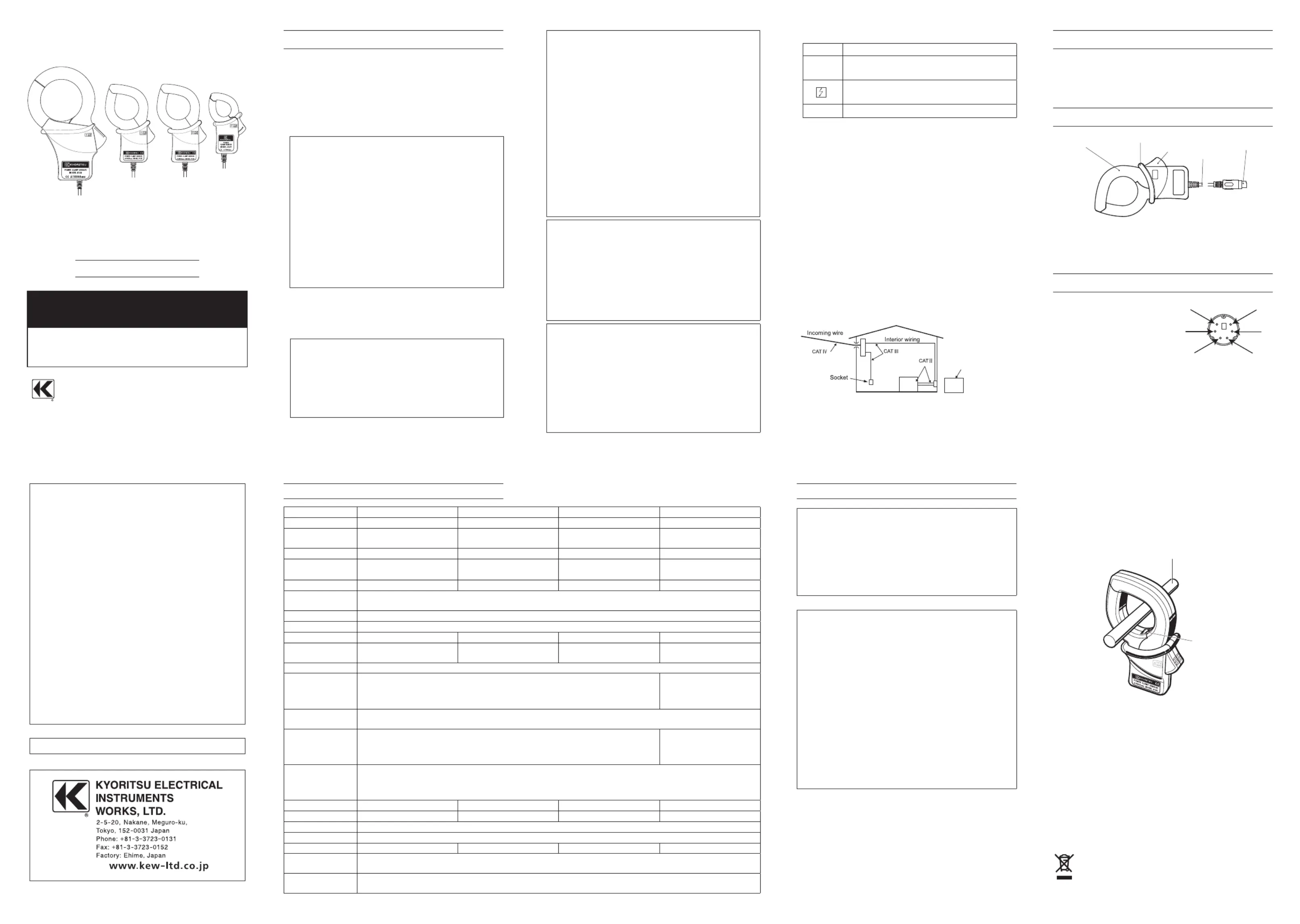
3. Instrument layout
TransformJaws
Barrier
Trigger
Cable
Outputconnector
Barrier:Itisapartprovidingprotectionagainst
electricalshockandensuringtheminimum
requiredairandcreepagedistances.
4. Din plug pin assignment
5
3
1
2
4
6
3
:GNDpin
5
:Outputsignalpin
1
,
2
,
4
and
6
:Nouse
*Abovefigureshowsthepinassignmentseeingthe
Clampsensorfromoutputconnectorpart.Thefigure
ofthepinassignmentofconnectionterminalis
symmetricaltoabovefigure.
6. Operating instructions
#
DANGER
●
Nevermakemeasurementonacircuitinwhichthe
electricalpotentialexceedsAC
300
VusingMODEL
8127
andAC
600
VusingMODEL
8124
,
8125
and
8126
inorder
toavoidpossibleshockhazard.
●
Thetransformerjawsaremadeofmetalandtheirtips
arenotcompletelyinsulated.Beespeciallycareful
aboutthepossibleshortingwherethemeasuredobject
hasexposedmetalparts.
#
CAUTION
●
Takesufficientcaretoavoidshock,vibrationor
excessiveforcewhenhandlingtheinstrument.
Otherwise,preciselyadjustedtransformerjawswillbe
damaged.
●
Whentransformerjawsdonotfullyclose,nevertryto
closethembyforce,butmakethemfreetomoveand
tryagain.Ifaforeignsubstanceisstuckinthejaw
tips,removeit.
●
Whenmakingcurrentmeasurements,keepthe
transformerjawsfullyclosed.
Otherwise,accuratemeasurementscannotbetaken.
Maximumconductorsizeisasfollows.
MODEL
8124
:
68
mmindiameter
MODEL
8125
/
8126
:
40
mmindiameter
MODEL
8127
:
24
mmindiameter
●
Holdtheinsertingpart(exceptforthecable)and
disconnecttheOutputconnectorfromthemeasuring
instrumentsoasnottocauseabreakinthecord.
6
-
1
Measurementprocedures
(
1
)ConnecttheOutputconnectortotheInputterminalof
themeasuringinstrument.
(
2
)PresstheTriggertoopenthetransformerjawsand
clampontooneconductor.
Inthiscase,themeasuredconductorshallbeatthecenter
ofthejaws.
WhenconnectingasensorwithaPowermeter(our
Powermeter,MODEL
6300
,etc.)matchthearrow
mark(Powersourcetoload),whichisindicatedonthe
transformerjaws,withthecurrentflowingdirectionin
ordertosynchronizethephasesofmeasuredcurrent
andoutputvoltage.
(
3
)Ensurethatthetipsoftransformerjawsarefirmly
closed.
Conductor
Load
Current direction
arrow
Power
source
6
-
2
SettingforPowermeter
WhenusinganyofthesesensorswithKEW
6305
or
6315
,pleaserefertotheinstructionmanual,eitherof
whichyou'reusing,andcarefullychecksensortype
settingsandavailablecurrentranges.
Thisinstrumentsatisfiesthemarking
requirementdefinedintheWEEEDirective
(
2002
/
96
/EC).Thissymbolindicatesseparate
collectionforelectricalandelectronic
equipment.
92
-
1640
E
5
-
22
DISTRIBUTOR
Kyoritsureservestherightstochangespecificationsordesigns
describedinthismanualwithoutnoticeandwithoutobligations.
Model
8124812581268127
RatedvoltageAC
1000
Arms(
1414
Apeak)AC
500
Arms(
707
Apeak)AC
200
Arms(
283
Apeak)AC
100
Arms(
141
Apeak)
OutputvoltageAC
0
〜
500
mV
(AC
500
mV/AC
1000
A):
0
.
5
mV/A
AC
0
〜
500
mV
(AC
500
mV/AC
500
A):
1
mV/A
AC
0
〜
500
mV
(AC
500
mV/AC
200
A):
2
.
5
mV/A
AC
0
〜
500
mV
(AC
500
mV/AC
100
A):
5
mV/A
MeasuringrangeAC
0
〜
1000
AAC
0
〜
500
AAC
0
〜
200
AAC
0
〜
100
A
Accuracy
(Input:sinewave)
±
0
.
5
%rdg
±
0
.
2
mV(
50
/
60
Hz)
±
1
.
5
%rdg
±
0
.
4
mV(
40
〜
1
kHz)
±
0
.
5
%rdg
±
0
.
1
mV(
50
/
60
Hz)
±
1
.
0
%rdg
±
0
.
2
mV(
40
〜
1
kHz)
±
0
.
5
%rdg
±
0
.
1
mV(
50
/
60
Hz)
±
1
.
0
%rdg
±
0
.
2
mV(
40
〜
1
kHz)
±
0
.
5
%rdg
±
0
.
1
mV(
50
/
60
Hz)
±
1
.
0
%rdg
±
0
.
2
mV(
40
〜
1
kHz)
Phasecharacteristics
±
1
degwithin(at
10
〜
1000
A/
45
〜
65
Hz)
±
1
degwithin(at
5
〜
500
A/
45
〜
65
Hz)
±
1
degwithin(at
2
〜
200
A/
45
〜
65
Hz)
±
2
degwithin(at
1
〜
100
A/
45
〜
65
Hz)
Temperature&humidityrange
(Guaranteedaccuracy)
23
±
5
℃
,relativehumidity:
85
%orless(nocondensation)
Operatingtemperaturerange
0
〜
50
℃
,relativehumidity:
85
%orless(nocondensation)
Storagetemperaturerange
-
20
〜
60
℃
,relativehumidity:
85
%orless(nocondensation)
Maximumpermissibleinput
AC
1000
Armscontinuous(
50
/
60
Hz)
AC
500
Armscontinuous(
50
/
60
Hz)AC
200
Armscontinuous(
50
/
60
Hz)AC
100
Armscontinuous(
50
/
60
Hz)
Output
impedance
Approx.
1
Ω
Approx.
2
Ω
Approx.
5
Ω
Approx.
11
Ω
LocationforuseAltitudeupto
2000
m,Indoors
Applicable
standards
IEC
61010
-
1
,IEC
61010
-
2
-
032
MeasurementCAT
Ⅲ
(
600
Vrms)
Pollutiondegree
2
IEC
61326
-
1
(EMC)
IEC
61010
-
1
,IEC
61010
-
2
-
032
MeasurementCAT
Ⅲ
(
300
Vrms)
Pollutiondegree
2
IEC
61326
-
1
(EMC)
Environmental
standards
EURoHSDirectivecompliant
Withstand
voltage
AC
5160
Vrms(
50
/
60
Hz)for
5
sec.
betweenJawandenclosure
betweenenclosureandoutputterminal
betweenJawandoutputterminal
AC
3470
Vrms(
50
/
60
Hz)for
5
sec.
betweenJawandenclosure
betweenenclosureandoutputterminal
betweenJawandoutputterminal
Insulation
resistance
50
M
Ω
orgreaterat
1000
V
betweenJawandenclosure
betweenenclosureandoutputterminal
betweenJawandoutputterminal
ConductorSize
Approx.
68
mmindiameter(max.)Approx.
40
mmindiameter(max.)Approx.
40
mmindiameter(max.)Approx.
24
mmindiameter(max.)
Dimension
186
(L)
×
129
(W)
×
53
(D)
mm
128
(L)
×
81
(W)
×
36
(D)
mm
128
(L)
×
81
(W)
×
36
(D)
mm
100
(L)
×
60
(W)
×
26
(D)
mm
CablelengthApprox.
3
m
OutputterminalMINIDIN
6
PIN
WeightApprox.
510
gApprox.
260
gApprox.
260
gApprox.
160
g
AccessoriesInstructionmanual
Cablemarker
OptionMODEL
7146
(
Banans
Φ
4
adjusterplug
)
MODEL
7147
(
Extensioncable
)
5. Specifications
Produktspezifikationen
| Marke: | Kyoritsu |
| Kategorie: | Messung |
| Modell: | 8125 |
Brauchst du Hilfe?
Wenn Sie Hilfe mit Kyoritsu 8125 benötigen, stellen Sie unten eine Frage und andere Benutzer werden Ihnen antworten
Bedienungsanleitung Messung Kyoritsu

11 September 2025
11 September 2025
11 September 2025
11 September 2025
10 September 2025
10 September 2025
9 September 2025
9 September 2025
9 September 2025
9 September 2025
Bedienungsanleitung Messung
Neueste Bedienungsanleitung für -Kategorien-
1 April 2026
31 März 2026
31 März 2026
31 März 2026
30 März 2026
30 März 2026
30 März 2026
30 März 2026
29 März 2026
29 März 2026