Kyoritsu KEW 8147 Bedienungsanleitung
Lies die bedienungsanleitung für Kyoritsu KEW 8147 (1 Seiten) kostenlos online; sie gehört zur Kategorie Messung. Dieses Handbuch wurde von 13 Personen als hilfreich bewertet und erhielt im Schnitt 4.8 Sterne aus 5 Bewertungen. Hast du eine Frage zu Kyoritsu KEW 8147 oder möchtest du andere Nutzer dieses Produkts befragen? Stelle eine Frage
Seite 1/1
INSTRUCTIONMANUAL
KEW 8146/8147/8148
LEAKAGE CLAMP SENSOR
Series
KYORITSU ELECTRICAL INSTRUMENTS WORKS, LTD.,
TOKYO, JAPAN
KEW
8146
KEW
8147
KEW
8148
LEAKAGECLAMPSENSOR
1. Safety warnings
Thisinstrumenthasbeendesigned,manufacturedand
testedaccordingtoIEC
61010
:Safetyrequirementsfor
ElectronicMeasuringapparatus,anddeliveredinthebest
conditionafterpassingqualitycontroltests.This
instructionmanualcontainswarningsandsafetyrules
whichhavetobeobservedbytheusertoensuresafe
operationoftheinstrumentandtomaintainitinsafe
condition.Therefore,readthroughtheseoperating
instructionsbeforeusingtheinstrument.
# WARNING
●
Readthroughandunderstandinstructionscontainedin
thismanualbeforeusingtheinstrument.
●
Keepthemanualathandtoenablequickreference
whenevernecessary.
●
Theinstrumentistobeusedonlyinitsintended
applications.
Theoperatinginstructionsdescribedinthemanualmust
beobserved.
●
Understandandfollowallthesafetyinstructions
containedinthemanual.
Itisessentialthattheaboveinstructionsareadheredto.
Failuretofollowtheaboveinstructionsmaycauseinjury
andorinstrumentdamage.
Kyoritsuisbynomeansliableforanydamageresulting
fromtheinstrumentincontradictiontothiscautionary
note.
Thesymbol
#
indicatedontheinstrument,meansthat
theusermustrefertotherelatedpartsinthemanualfor
safeoperationoftheinstrument.Itisessentialtoreadthe
instructionswhereverthe
#
symbolappearsinthe
manual.
#
DANGER
isreservedforconditionsandactionsthat
arelikelytocauseseriousorfatalinjury.
#
WARNING
isreservedforconditionsandactions
thatcancauseseriousorfatalInjury.
#
CAUTION
isreservedforconditionsandactionsthat
cancauseminorinjuryorinstrumentdamage.
#
DANGER
●
Nevermakemeasurementonacircuitinwhichthe
electricalpotentialexceedsAC
300
V.
●
Donotmakemeasurementwhenthunderrumbling.Ifthe
instrumentisinuse,stopthemeasurementimmediately
andremovetheinstrumentfromthemeasuredobject.
●
Donotattempttomakemeasurementinthepresenceof
flammablegasses.Otherwise,theuseoftheinstrument
maycausesparking,whichcanleadtoanexplosion.
●
Thetransformerjawsaremadeofmetalandtheirtips
arenotcompletelyinsulated.Beespeciallycareful
aboutthepossibleshortingwherethemeasuredobject
hasexposedmetalparts.
●
Neverattempttousetheinstrumentifit'ssurfaceor
yourhandarewet.
●
Donotexceedthemaximumallowableinputofany
measuringrange.
# WARNING
●
Neverattempttomakeanymeasurement,ifany
abnormalconditionsarenoted,suchasbrokencase,
andexposedmetalparts.
●
Donotinstallsubstitutepartsormakeanymodification
totheinstrument.
Returntheinstrumenttothedistributorfromwhoyou
purchasedthisinstrumentforrepairorre-calibrationin
caseofsuspectedfaultyoperation.
●
Alwayskeepyourfingersandhandsbehindthebarrier
ontheinstrumenttoavoidthepossibleshockhazard.
# CAUTION
●
Donotsteponorpinchthecordtopreventthejacketof
cordfrombeingdamaged.
●
Theoutputconnectorshallberemovedorconnected
withoutclampingaconductor.Otherwise,itmaycause
afailure.
●
Donotexposetheinstrumenttodirectsunlight,high
temperatures,humidityordew.
●
Nevergiveshocks,suchasvibrationordrop,whichmay
damagetheinstrument.
●
Useadampclothanddetergentforcleaningthe
instrument.Donotuseabrasivesorsolvents.
Safetysymbols
Incoming wire
O:
Device which is
not directly
connected to the
mains power supply
Socket
Interior wiring
○
MeasurementCategory:
Toensuresafeoperationofmeasuringinstruments,
IEC
61010
establishessafetystandardsforvarious
electricalenvironments,categorizedasOtoCATIV,
andcalledmeasurementcategories.Higher-numbered
categoriescorrespondtoelectricalenvironmentswith
greatermomentaryenergy,soameasuringinstrument
designedforCATIIIenvironmentscanenduregreater
momentaryenergythanonedesignedforCATII.
O:Circuitswhicharenotdirectlyconnectedtothe
mainspowersupply.
CATII:Electricalcircuitsofequipmentconnectedtoan
ACelectricaloutletbyapowercord.
CATIII:Primaryelectricalcircuitsoftheequipment
connecteddirectlytothedistributionpanel,and
feedersfromthedistributionpaneltooutlets.
CATIV:Thecircuitfromtheservicedroptotheservice
entrance,andtothepowermeterandprimary
over-currentprotectiondevice(distribution
panel).
2. Features
●
ClampsensorforACleakagecurrentmeasurement.
●
Canmeasureupto:
KEW
8146
:
30
A
KEW
8147
:
70
A
KEW
8148
:
100
A
●
DesignedtointernationalsafetystandardIEC
61010
-
2
-
032
CAT
Ⅲ
PollutionDegree
2
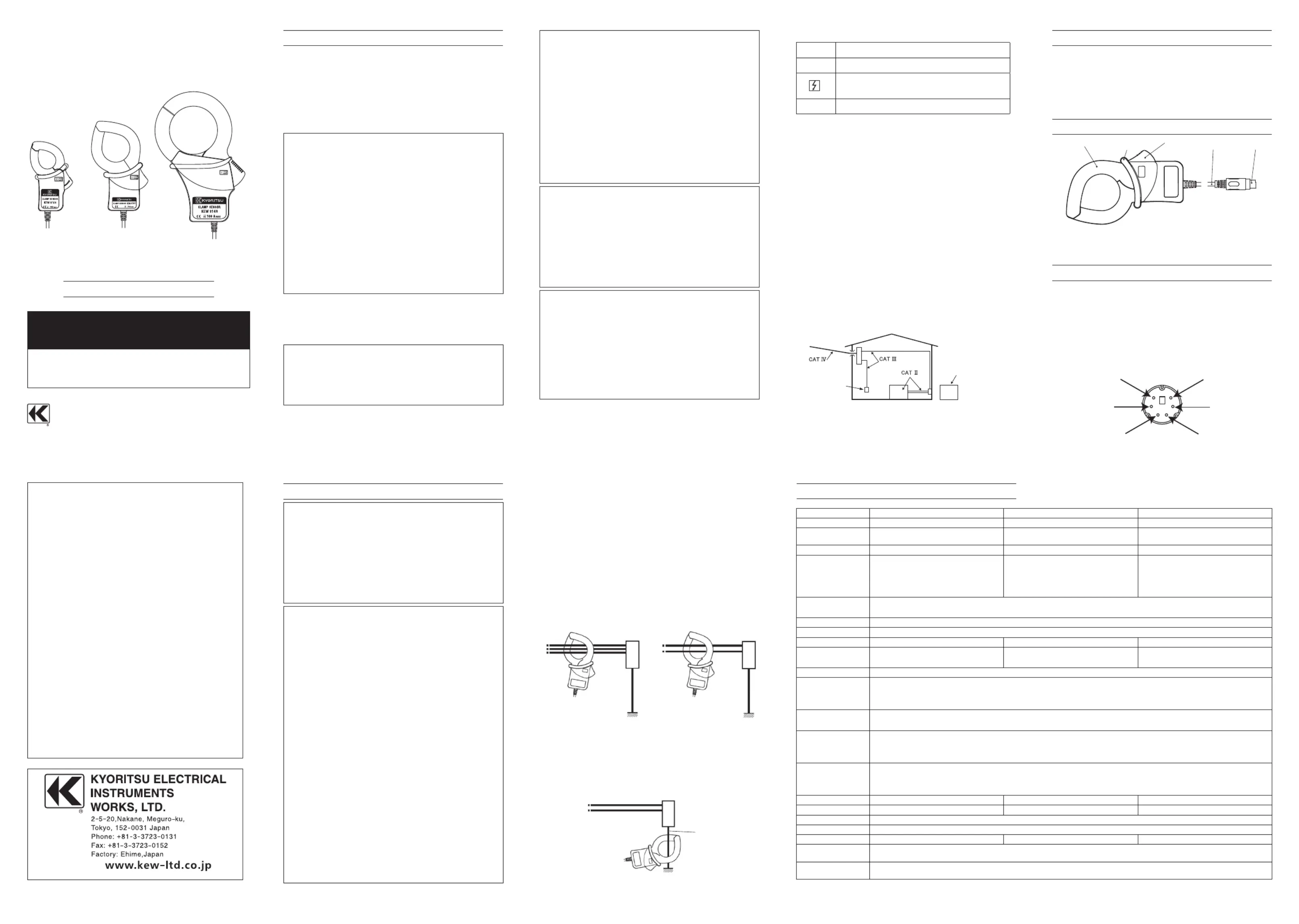
3. Instrument layout
TransformJaws
Trigger
Cable
Outputconnector
Barrier
Barrier
:
Itisapartprovidingprotectionagainstelectrical
shockandensuringtheminimumrequiredairand
creepagedistances.
4. DIN Plug pin assignment
3
:GNDpin
5
:Outputsignalpin
6
:SensorSignalpin
(
Resistancebetween
3
Pinand
6
Pin:
8146
:
47
k
Ω
8147
:
8
.
2
k
Ω
8148
:
30
k
Ω)
1
,
2
and
4
:Nouse
*LowerfigureshowsthepinassignmentseeingtheClamp
sensorfromoutputconnectorpart.Thefigureofthepin
assignmentofconnectionterminalissymmetricaltolower
figure.
5
3
1
2
4
6
5. Operating instructions
#
DANGER
●
Nevermakemeasurementonacircuitinwhichthe
electricalpotentialexceedsAC
300
Vinordertoavoid
possibleshockhazard.
●
Thetransformerjawsaremadeofmetalandtheirtips
arenotcompletelyinsulated.Beespeciallycareful
aboutthepossibleshortingwherethemeasuredobject
hasexposedmetalparts.
●
Keepyourfingersandhandsbehindthebarrierduringa
measurement.
#
CAUTION
●
Takesufficientcaretoavoidshock,vibrationor
excessiveforcewhenhandlingtheinstrument.
Otherwise,preciselyadjustedtransformerjawswillbe
damaged.
●
Whentransformerjawsdonotfullyclose,nevertryto
closethembyforce,butmakethemfreetomoveand
tryagain.Ifaforeignsubstanceisstuckinthejaw
tips,removeit.
●
Whenmakingcurrentmeasurements,keepthe
transformerjawsfullyclosed.
Otherwise,accuratemeasurementscannotbetaken.
●
Holdtheinsertingpart(exceptforthecable)and
disconnecttheOutputconnectorfromthemeasuring
instrumentsoasnottocauseabreakinthecord.
●
Whenmeasuringcurrentwhichpulseelementis
superposed,differencesoftheindicatedvaluemaybe
causedbetweenranges,ifthepeakvalueexceedsthe
measurementrangetoalargeextent.Inthis
case,the
readingatthebiggerrangeshouldbetaken
asaright
value.SensitivetransformerjawsareusedforLeakage
clampmeter.Becauseofthecharacteristicsof
transformerjaws,whichcanbeopenedandclosed,it
isimpossibletoeliminatetheinterferenceofexternal
magneticfieldcompletely.Ifthereisapresenceof
strongmagneticfield,usetheinstrumentatadistance
asfaraspossiblefromit.Followingarethetypical
thingsgeneratingmagneticfield.
・
Conductorfedlargecurrent
・
Motor
・
Equipmentwhichhasmagnet
・
Integratingwattmeter
5
-
1
Measuringmethod
(
1
)
ConnecttheOutputconnectortotheInputterminalof
themeasuringinstrument.
(
2
)PresstheTriggertoopenthetransformerjawsand
clampontooneconductor.
Inthiscase,themeasuredconductorshallbeatthe
centerofthejaws.
(
3
)
Ensurethatthetipsoftransformerjawsarefirmlyclosed.
5
-
2
Measuringmethod
(
1
)Measuringoutofbalanceleakagecurrent(See
Fig.
1
):Clampontoallconductorsexceptagrounded
wire.
(
2
)Measuringearthleakagecurrent(SeeFig.
2
):Clamp
ontoagroundedwire.
3
-phase
3
-wiresystem
(In
4
-wiresystemwithneutral,
clampontoall
4
wires)
Fig.
1
Measuringoutofbalanceleakagecurrent
Groundedwire
Load
Load
Load
Single-phase
2
-wiresystem
(In
3
-wiresystemwithneutral,
clampontoall
3
wires)
Fig.
2
Measuringearthleakagecurrent
92
-
1746
E
7
-
22
DISTRIBUTOR
#
Refertotheinstructionsinthemanual.
IndicatesaInstrumentwithdoubleorreinforcedinsulation
Indicatesthatthisinstrumentcanclamponlivebare
conductorswhenthevoltagetobetestedisbelow
Circuit-Ground-to-Earthvoltageagainsttheindicated
MeasurementCategory.
~
IndicatesAC
Model
KEW
8146
KEW
8147
KEW
8148
RatedvoltageAC
30
Arms(
42
.
4
Apeak)AC
70
Arms(
99
.
0
Apeak)AC
100
Arms(
141
.
4
Apeak)
Outputvoltage
AC
0
〜
1500
mV
(
50
mV/A)
AC
0
〜
3500
mV
(
50
mV/A)
AC
0
〜
5000
mV
(
50
mV/A)
MeasuringrangeAC
0
〜
30
AAC
0
〜
70
AAC
0
〜
100
A
Accuracy
(Input:sinewave)
0
A
〜
15
A
±
1
.
0
%rdg
±
0
.
1
mV(
50
/
60
Hz)
±
2
.
0
%rdg
±
0
.
2
mV(
40
〜
1
kHz)
15
A
〜
30
A
±
5
.
0
%rdg(
50
/
60
Hz)
±
10
.
0
%rdg(
45
〜
1
kHz)
0
A
〜
40
A
±
1
.
0
%rdg
±
0
.
1
mV(
50
/
60
Hz)
±
2
.
0
%rdg
±
0
.
2
mV(
40
〜
1
kHz)
40
A
〜
70
A
±
5
.
0
%rdg(
50
/
60
Hz)
±
10
.
0
%rdg(
45
〜
1
kHz)
0
A
〜
80
A
±
1
.
0
%rdg
±
0
.
1
mV(
50
/
60
Hz)
±
2
.
0
%rdg
±
0
.
2
mV(
40
〜
1
kHz)
80
A
〜
100
A
±
5
.
0
%rdg(
50
/
60
Hz)
±
10
.
0
%rdg(
45
〜
1
kHz)
Temperature&humidityrange
(Guaranteedaccuracy)
23
±
5
℃
,relativehumidity:
85
%orless(nocondensation)
Operatingtemperaturerange
0
〜
50
℃
,relativehumidity:
85
%orless(nocondensation)
Storagetemperaturerange
-
20
〜
60
℃
,relativehumidity:
85
%orless(nocondensation)
Maximumpermissibleinput
AC
30
Armscontinuous(
50
/
60
Hz)AC
70
Armscontinuous(
50
/
60
Hz)AC
100
Armscontinuous(
50
/
60
Hz)
Output
impedance
Approx.
90
Ω
Approx.
100
Ω
Approx.
60
Ω
Locationforuse
Altitudeupto
2000
m,Indoors
Applicable
standards
IEC
61010
-
1
,IEC
61010
-
2
-
032
MeasurementCAT
Ⅲ
(
300
Vrms)
Pollutiondegree
2
IEC
61326
-
1
(EMC)
Environmental
standards
EURoHSdirectivecompliant
Withstand
voltage
AC
3470
Vrms(
50
/
60
Hz)for
5
sec.
betweenJawandenclosure
betweenenclosureandoutputterminal
betweenJawandoutputterminal
Insulation
resistance
50
M
Ω
orgreaterat
1000
V
betweenJawandenclosure
betweenenclosureandoutputterminal
betweenJawandoutputterminal
ConductorSize
Approx.
24
mmindiameter(max.)
Approx.
40
mmindiameter(max.)
Approx.
68
mmindiameter(max.)
Dimension
100
(L)
×
60
(W)
×
26
(D)mm
128
(L)
×
81
(W)
×
36
(D)mm
186
(L)
×
129
(W)
×
53
(D)mm
Cablelength
Approx.
2
m
OutputterminalMINIDIN
6
PIN
Weight
Approx.
150
gApprox.
240
gApprox.
510
g
Accessories
Instructionmanual
Cablemarker
Option
MODEL
7146
(
Banana
Φ
4
adjusterplug
)
MODEL
7185
(
Extensioncable
)
6. Specifications
Produktspezifikationen
| Marke: | Kyoritsu |
| Kategorie: | Messung |
| Modell: | KEW 8147 |
Brauchst du Hilfe?
Wenn Sie Hilfe mit Kyoritsu KEW 8147 benötigen, stellen Sie unten eine Frage und andere Benutzer werden Ihnen antworten
Bedienungsanleitung Messung Kyoritsu

11 September 2025
11 September 2025
11 September 2025
11 September 2025
10 September 2025
10 September 2025
9 September 2025
9 September 2025
9 September 2025
9 September 2025
Bedienungsanleitung Messung
Neueste Bedienungsanleitung für -Kategorien-
1 April 2026
31 März 2026
31 März 2026
31 März 2026
30 März 2026
30 März 2026
30 März 2026
30 März 2026
29 März 2026
29 März 2026