Kyoritsu KEW 8133 Bedienungsanleitung
Lies die bedienungsanleitung für Kyoritsu KEW 8133 (24 Seiten) kostenlos online; sie gehört zur Kategorie Messung. Dieses Handbuch wurde von 20 Personen als hilfreich bewertet und erhielt im Schnitt 4.9 Sterne aus 7 Bewertungen. Hast du eine Frage zu Kyoritsu KEW 8133 oder möchtest du andere Nutzer dieses Produkts befragen? Stelle eine Frage
Seite 1/24
2. Features
●
This is a clamp sensor which can measure AC current up to 3000 A.
●Flexible and lightweight is achieved by using air core coil for the
sensor.
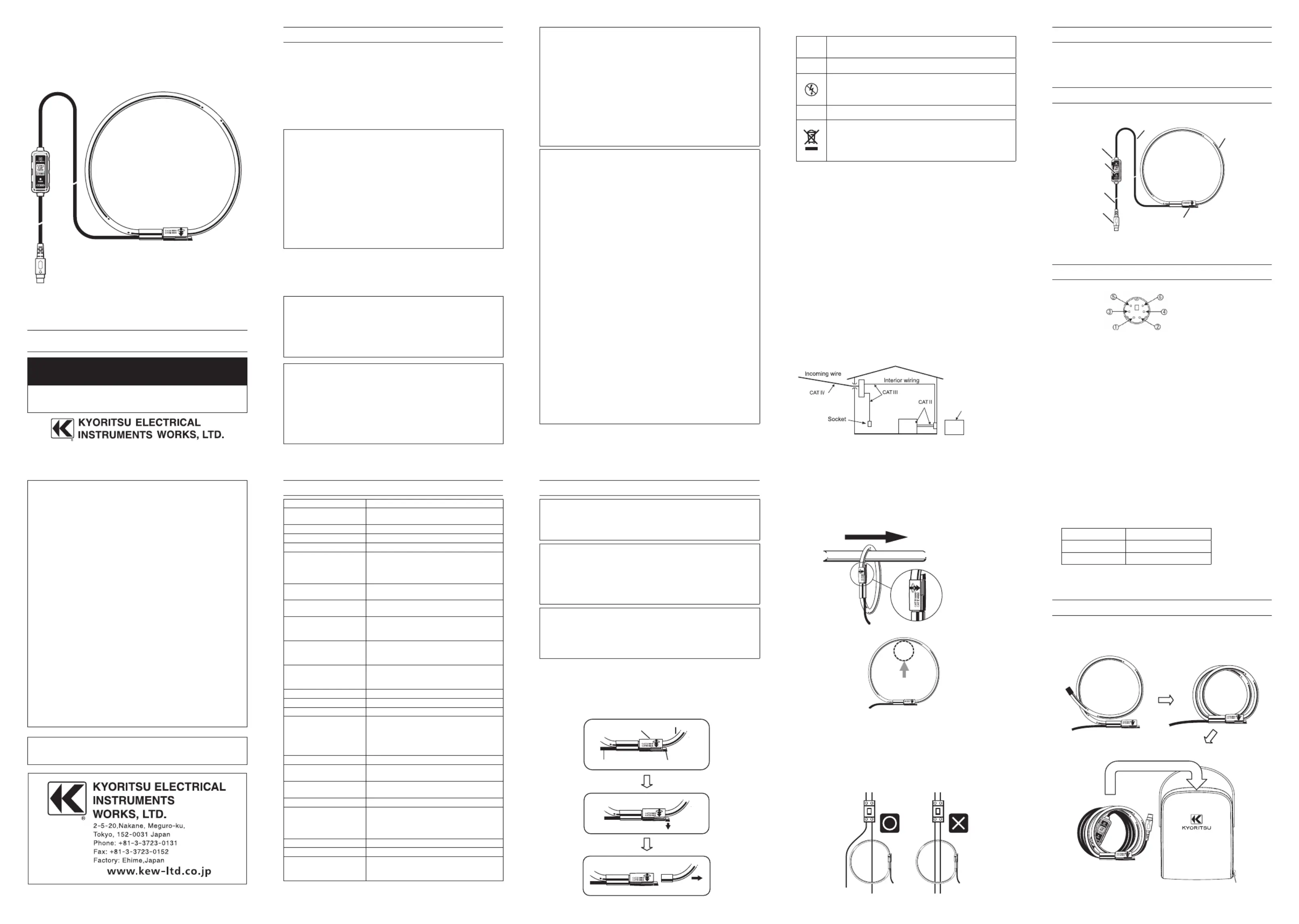
3. Clamp sensor layout
4. Pin assignment for output terminal
* Pin assignment at the connecting terminal of measuring instrument
is symmetrical to above figure.
●③⑤ Output signal passes between and of output terminal.
●This clamp sensor drives power via the output cable. Power
supply of +3.0 to +5.5V is required between and of output ①③
terminal and -3.0 to -5.5V is required between and .②③
#WARNING
●
Stop using the sensor if any visible damage such as cracks on the
circuit box or clamp part, or exposed internal metal parts are
found.
● Do not disassemble, install substitute parts or make any
modification to the clamp sensor. Return the clamp sensor to
your local KYORITSU distributor for repair or re-calibration in
case of suspected faulty operation.
●Do not use the clamp sensor if the sensor or your hand is wet;
otherwise, electrical shock accident may occur.
●Comply with the local and national safety code and use the
protective gears to prevent shock hazard.
#CAUTION
●Do not step on or pinch the cord; it may damage the jacket of
the cable.
●Do not expose the clamp sensor to direct sunlight, high
temperature, humidity or dew. It may cause deformation or
insulation degradation and cannot meet the original
specification.
●Not to give shocks, such as vibration or drop, which may
damage the clamp sensor, during transit or use.
● Use a damp cloth with water or neutral detergent for cleaning
the clamp sensor. Do not use abrasives or solvents.
● This clamp sensor is not designed to be dust or waterproof. Do
not use it dusty places or where the clamp sensor is likely to be
wet. It can damage the sensor.
● Never pinch foreign matters or give vibrations to the joint part of
the clamp sensor; otherwise, the joint part may be damaged
and lead to inaccurate measurements.
●Do not bend or pull the root of the cable to prevent breaks in the
cable.
●Never apply a current exceeding the measuring range for a long
time. It may damage the clamp sensor.
●Do not connect/remove the connectors while the connected
devices are on or clamping onto the conductor under test.
Otherwise, the connected device or clamp sensor may be
damaged.
●Accurate measurement may not be obtained in the vicinity of
strong magnetic fields such as transformers, high-current
circuits or wireless machines.
1. Safety warnings
This clamp sensor has been designed and tested according to
IEC61010-1: Safety Requirements for Electronic Measuring
Apparatus, and delivered in the best condition after passing quality
control tests. This instruction manual contains warnings and safety
rules which have to be observed by the user to ensure safe operation
of the clamp sensor and to maintain it in safe condition. Therefore,
read through these operating instructions before starting to use the
clamp sensor.
# WARNING
●Read through and understand instructions contained in this
manual before starting to use the clamp sensor.
● Keep the manual at hand to enable quick reference whenever
necessary.
●The clamp sensor is to be used only in its intended applications.
●Understand and follow all the safety instructions contained in
the manual.
It is essential that the above instructions are adhered to. Failure to
follow the above instructions may cause injury, clamp sensor damage
and/or damage to equipment under test. KYORITSU is not liable for
any damage resulting from the mishandling of the clamp sensor.
The symbol indicated on the clamp sensor, means that the user #
must refer to the related parts in the manual for safe operation of the
clamp sensor. It is essential to read the instructions wherever the #
symbol appears in the manual.
#DANGER: is reserved for conditions and actions that are
likely to cause serious or fatal injury.
#WARNING: is reserved for conditions and actions that can
cause serious or fatal injury.
#CAUTION: is reserved for conditions and actions that can
cause injury or instrument damage.
#DANGER
●Do not make measurements on a circuit in which electrical
potentials exceeding the following values exist: 300 V in CAT IV
environment and 600 V in CAT III or lower environment.
●Use the sensor only as specified; otherwise, the protection
supplied by the sensor can be compromised and damage itself
or lead to a serious accident. Always verify the proper operation
on a well-known power source before starting to use the sensor.
Meaning of symbols on the clamp sensor:
#
User must refer to the explanations in the instruction
manual for safety reasons.
Clamp sensor with double or reinforced insulation
Do not use for, attach to or detach from un-insulated
hazardous live conductors, which may render electric
shock, electric burn, or arc flash.
AC
Crossed-out wheel bin symbol (according to WEEE
Directive: 2002/ 96/ EC) indicating that this electrical
product may not be treated as household waste, but that
it must be collected and treated separately.
Measurement Category:
To ensure safe operation of measuring instruments, IEC 61010
establishes safety standards for various electrical environments,
categorized as O to CAT IV, and called measurement categories.
Higher-numbered categories correspond to electrical environments
with greater momentary energy, so a measuring instrument designed
for CAT III environments can endure greater momentary energy than
one designed for CAT II.
O (None, Other)
: Circuits which are not directly connected to the mains
power supply.
CAT II : Electrical circuits of equipment connected to an AC
electrical outlet by a power cord.
CAT III : Primary electrical circuits of the equipment connected
directly to the distribution panel, and feeders from the
distribution panel to outlets.
CAT IV : The circuit from the service drop to the service
entrance, and to the power meter and primary over-
current protection device (distribution panel).
5. Specifications
Model nameKEW 8133
Applicable models
KEW 6305 Power Meter
KEW 6315 Power Quality Analyzer
Rated current3000 A AC
Output voltage500 mV AC/ 3000 A AC (0.167 mV/ A)
Measuring range0 – 3000 A AC rms (5515 A Peak)
Accuracy
(sine wave input)
±1.0%rdg±0.5mV (45 – 65 Hz)
±1.5%rdg±0.5mV (40 – 1 kHz)
*
±3.0%rdg±0.5mV (max): electromagnetic
environment on industrial site
Phase characteristics
45 – 65 Hz: within ±2°
40 – 1 kHz: within ±3°
Current consumption
(at power supply ±5V)
2 mA (max)
Temp. & Hum. range
(guaranteed accuracy)
23±5°C
Relative humidity 85% or less
(no condensation)
Operating Temp. &
Hum. range
-10 to 50°C
Relative humidity 85% or less
(no condensation)
Storage Temp. & Hum.
range
-20 to 60°C
Relative humidity 85% or less
(no condensation)
Max allowable input3900 A AC (continuous)
Output impedance100 Ω or less
Environmental conditionAltitude up to 2000 m, In-door use
Applicable standards
IEC61010-1
IEC61010-2-032
CAT III (600 V rms), CAT IV (300 V rms),
Pollution degree 2
IEC 61326-1 (EMC)
Environmental standardsEU RoHS directive compliant
Withstand voltage
5160 V AC rms (50/ 60 Hz)/ 5 sec.
Between circuit and clamp sensor
Insulation resistance
50 M or more/ 1000 VΩ
Between circuit and clamp sensor
Measurable conductor size
Ø 170 mm (max)
Cable length
Approx. 2.7m: between circuit box and
clamp sensor
Approx. 0.2m: between circuit box and
output terminal
Output terminalMINI DIN 6PIN
WeightApprox. 200 g
Accessories
Carrying bag (MODEL9095)
Instruction manual
Cable marker No.1 - No.3 (2pcs each)
6. Operating instructions
#DANGER
●Never make measurements on a circuit in which electrical
potentials exceeding the following values exist: 300 V in CAT IV
and 600 V in CAT III or lower environment.
#CAUTION
●The measurable conductor size is 170mm in diameter (max).
Make sure that the clamp sensor is firmly closed for accurate
measurement.
●
When disconnecting the output terminal from the measuring
instrument, do so by removing the plug and not by pulling the cable.
Note
●This sensor has been specially designed and dedicated to our
Power meter KEW 6305 and Power quality analyzer KEW 6315.
It cannot be used with the other our products such as KEW
5010/ 5020.
6-1 Measurement method
⑴Connect the output terminal to the input terminal on the
measuring instrument.
⑵ Power on the measuring instrument.
⑶ Unlock the Joint according to the following illustrations.
⑷Clamp onto one conductor to be tested. Locate the conductor as
shown below while observing the direction of the Guide arrow
mark - indicating the current flowing direction - marked on the
Joint of the sensor to synchronize the phases of the current under
test and of the output voltage.
⑸ Ensure that the joint part of the clamp sensor is firmly locked.
● Joint part may be unlocked and disconnected if excessive force
is applied to.
● Clamp onto just one conductor; measurements cannot be
made when clamping single-phase (2-wire) or three-phase
(3-wire) at the same time.
6-2 Connecting with KEW 6305/KEW 6315
Before connecting this sensor with KEW 6305 or KEW 6315,
confirm that the internal firmware version is later than the one
listed in the following table; otherwise, this sensor cannot be used
with. The latest firmware is available on our website.
MODELFirmware version
KEW 6305V1.10 or later
KEW 6315V1.50 or later
For the detailed settings of the clamp sensor, please refer to the
instruction manual for the applicable model.
7. Storage
Wind the cable of the sensor as shown below and lock the joint.
Wind the black cable in the same way and store them in the carrying
bag.
FLEXIBLE CLAMP SENSOR
POWER CLAMP SENSOR Series
KEW 8133
8-22 92-2322A
DISTRIBUTOR
Kyoritsu reserves the rights to change specifications or designs
described in this manual without notice and without obligations.
O: Device which is
not directly
connected to the
mains power supply
Instruction manual
Joint
Clnsamp seor
Cable
Ciuit box rc
Power indicator
Output cable
Output terminal
Power pply (+V) su
Posu(-V)wer pply
COM
Output signal
NC (Noconnected) t
Sensor identification (110kΩ)
Joint
Clamp sensor
Lock
Cable
1. Press
2. ck Unlo
Lo ad
Source
Guide aw mark rro
Reference position of
condtor to be tested uc
Positionhe conductor to be tested illustrated above. tas
Caying b rrag
Produktspezifikationen
| Marke: | Kyoritsu |
| Kategorie: | Messung |
| Modell: | KEW 8133 |
Brauchst du Hilfe?
Wenn Sie Hilfe mit Kyoritsu KEW 8133 benötigen, stellen Sie unten eine Frage und andere Benutzer werden Ihnen antworten
Bedienungsanleitung Messung Kyoritsu

11 September 2025
11 September 2025
11 September 2025
11 September 2025
10 September 2025
10 September 2025
9 September 2025
9 September 2025
9 September 2025
9 September 2025
Bedienungsanleitung Messung
Neueste Bedienungsanleitung für -Kategorien-
1 April 2026
31 März 2026
31 März 2026
31 März 2026
30 März 2026
30 März 2026
30 März 2026
30 März 2026
29 März 2026
29 März 2026