Phase Technology P350 Bedienungsanleitung
Lies die bedienungsanleitung für Phase Technology P350 (4 Seiten) kostenlos online; sie gehört zur Kategorie Empfänger. Dieses Handbuch wurde von 47 Personen als hilfreich bewertet und erhielt im Schnitt 4.9 Sterne aus 5 Bewertungen. Hast du eine Frage zu Phase Technology P350 oder möchtest du andere Nutzer dieses Produkts befragen? Stelle eine Frage
Seite 1/4
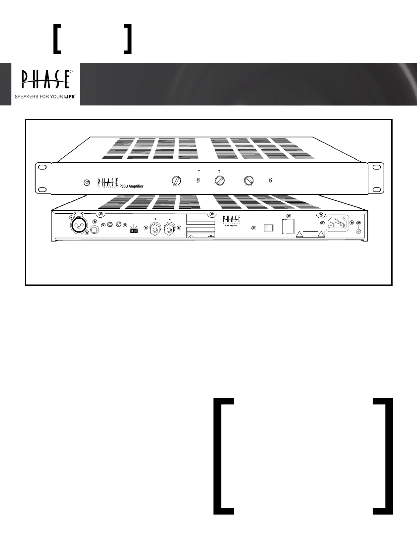
INPUT
12V TRIGGER
UNBALANCEDBALANCED
OUTPUT
TRIGGER
MODE
INOUT
MUSIC
ON
12V
4-16 OHMS
INPUT
VOLTAGE
POWER
ONOFF
115V 60 Hz/ 230V 50 Hz
AC INPUT 600W MAX
PUSH
115V
P350 CLASS-G HIGH CURRENT MONO BLACK AMPLIFIER
TECHNOLOGY
R
OWNER’S MANUAL & INSTALL GUIDE
[FEATURES]• Soft Clipping (Subwoofer Mode) • Short Circuit / Overload • Thermostatic Variable Speed Fan Cooling
• Thermal Overload Protection • Transformer Thermal Protection • Over-Current Protection
Thank you for choosing Phase Technology
®
speakers. We
know there are a wide variety of choices available today, and
we sincerely appreciate your purchase of our product. Phase
Technology speakers are built to exacting standards and will
provide many years of listening enjoyment.
The P350 is the companion amplier to Phase Technology
custom in-wall subwoofer systems but its use is not limited
to only subwoofer applications. It also has the exibility of
operation as a full range high current, high performance,
mono-block audio power amplier.
Our speakers are the result of over ve decades of designing
and manufacturing. We hold many key patents in loudspeaker
technology including the soft-dome tweeter. Our mission, our
passion is to constantly advance the art and science of accurate
audio reproduction. Our dedication insures your new speakers
will accurately reproduce all the impact, detail and delicacy of
today’s digital technology.
Regardless of application, serious audiophile listening or home
theater, we recommend that you take the time to read this
manual thoroughly before connecting speakers to your amplier
or receiver. In the highly unlikely event that you should experience
a problem with set-up or operation, please contact one of our
authorized dealers for assistance, or contact us directly.
Phase Technology
®
Corporation
8005 W. 110th St., Suite 208
Overland Park, KS 66210
855.663.5600 (Domestic)
+1.913.663.5600 (International)
Fax: 913.663.3200
BASS EQ
-3 dB+6 dB
IN
CROSSOVER
OUT
SUB FILTERLEVELPHASE
POWER
LFE120HZ
40
MINMAX
0
180
SAFETY INSTRUCTIONS 2
GETTING STARTED AND PRECAUTIONARY NOTES 2
SUBWOOFER PLACEMENT 3
SPEAKER CONNECTIONS 3
OPERATING INSTRUCTIONS & CONTROLS 3
RACK MOUNTING 4
CARING FOR YOUR SPEAKERS 4
MAINTENANCE AND SERVICE 4
TROUBLESHOOTING 4
WARRANTY 4
SPECIFICATIONS 4
P350subwoofer amplier
Produktspezifikationen
| Marke: | Phase Technology |
| Kategorie: | Empfänger |
| Modell: | P350 |
Brauchst du Hilfe?
Wenn Sie Hilfe mit Phase Technology P350 benötigen, stellen Sie unten eine Frage und andere Benutzer werden Ihnen antworten
Bedienungsanleitung Empfänger Phase Technology

20 Juli 2025
20 Juli 2025
Bedienungsanleitung Empfänger
Neueste Bedienungsanleitung für -Kategorien-
3 April 2026
2 April 2026
1 April 2026
31 März 2026
30 März 2026
30 März 2026
30 März 2026
30 März 2026
30 März 2026
29 März 2026