Pro1 T501M Bedienungsanleitung
Pro1 Thermostat T501M
Lies die bedienungsanleitung für Pro1 T501M (2 Seiten) kostenlos online; sie gehört zur Kategorie Thermostat. Dieses Handbuch wurde von 14 Personen als hilfreich bewertet und erhielt im Schnitt 4.5 Sterne aus 8 Bewertungen. Hast du eine Frage zu Pro1 T501M oder möchtest du andere Nutzer dieses Produkts befragen? Stelle eine Frage
Seite 1/2
T501M
Installation Manual
Pro1 Technologies
P.O. Box 3377
Springeld, MO 65804
Toll Free: 888-776-1427
Web: www.pro1iaq.com
Hours of Operation: M-F 9AM - 6PM Eastern
Installation Tips
Thermostat Application Guide
For Use On
Most 24V Heating and A/C Systems
Rev. 1810
®U.S. Registered Trademark. Patents pending
Copyright ©2018 All Rights Reserved.
Specications
Power Source ......................................... 18-30 VAC
Load Rating.............................................. 1 AMP per terminal,
1.5 AMP maximum on all
terminals combined
Operating Humidity ............................. 90% Non-condensing
maximum
Heat anticipator range ........................... 0.15A to 1.2A
Cool anticipator range ......................... Fixed
Millivolt ...................................................... 0.15A for 0.75 VDC systems
Temperature range ................................50˚ - 90˚ F ( 10˚ - 32˚ C )
Gas or Oil Heat
Electric Furnace
Heat Pump With NO Auxiliary Heat
Heat Only Systems
Cool Only Systems
Millivolt Systems
NOT For Use On
Multi Stage Systems
Line Voltage Systems
Compressors With No Built In Delay
3 Wire Hydronic Systems
Wiring
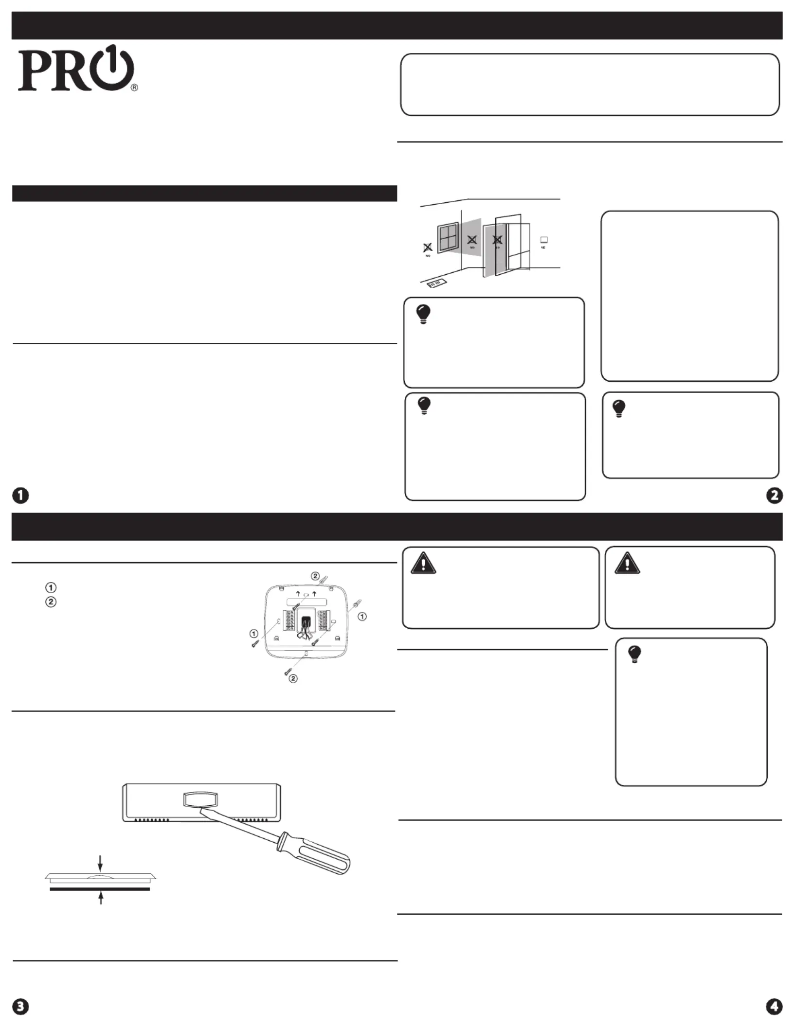
Subbase Installation
The thermostat should be installed approximately 4 to 5 feet above
the oor. Select an area with average temperature and good air
circulation.
• Close to hot or cold air ducts
• That are in direct sunlight
• With an outside wall behind
the thermostat
• In areas that do not require
conditioning
• Where there are dead spots
or drafts
(in corners or behind doors)
• Where there might be
concealed chimneys or pipes
Wall Locations
Vertical Mount
Horizontal Mount
For horizontal mount, install one left
screw and one right screw. For vertical
mount, install one top screw and one
bottom screw.
All of our products are mercury
free. However, if the product you
are replacing contains mercury,
dispose of it properly. Your local
waste management authority can
give you instructions on recycling
and proper disposal.
Pick an installation location that is
easy for the user to access. The
temperature of the location
should be representative of the
building.
Installation Tip
Mercury Notice
Do not install
thermostat in locations:
Failure to disconnect the power
before beginning to install this
product can cause electrical
shock or equipment damage.
Installation Tip:
Electrical Hazard
Caution: Electrical Hazard
All components of the control
system and the thermostat
installation must conform to
Class II circuits per the NEC Code.
Warning:
Do not overtighten terminal
block screws, as this can
damage the terminal block.
A damaged terminal block
can keep the thermostat
from tting on the subbase
correctly or cause system
operation issues.
Installation Tip
Max Torque = 6in-lbs.
Wiring
If you are replacing a thermostat, make
note of the terminal connections on
the thermostat that is being replaced.
In some cases the wiring connections
will not be color coded. For example,
the green wire may not be connected
to the terminal.G
Loosen the terminal block screws.
Insert wires then retighten terminal
block screws.
Place nonammable insulation into
wall opening to prevent drafts.
1.
2.
3.
Terminal Designations
O
Heat pump changeover valve
energized in cooling
Heat pump changeover valve
energized in heating
W
Heat relay
RH
Transformer power for heating
RC
Transformer power for cooling
G
Fan relay
Y
Compressor relay
Wiring Tips
RH & RC Terminals
For single transformer systems, leave
the jumper wire in place between
the RH and RC. Remove jumper wire
for two transformer systems.
Heat Pump Systems
If wiring to a heat pump, use a small
piece of wire (not supplied) to connect
terminals W and Y.
(With NO AUX or
Emergency Heat)
Wire Specications
Use 18-22 gauge thermostat wire.
Failure to disconnect the power before
beginning to install this product can
cause electrical shock or equipment
damage.
B
Removing The Private Label Badge
Gently slide a screwdriver into the bottom edge of the badge. Gently turn
the screwdriver counter clockwise. The badge is held on by a magnet in
the front plastic. The badge should pry o easily. DO NOT USE FORCE.
About The Badge
All of our thermostats use the same universal magnetic badge. Visit the company
website to learn more about our free private label program.
Magnet in front plastic
Use the bevel on bottom of badge
Private Label Badge
A trained, experienced technician must install this product.
Carefully read these instructions. You could damage this product or
cause a hazardous condition if you fail to follow these instructions.
Produktspezifikationen
| Marke: | Pro1 |
| Kategorie: | Thermostat |
| Modell: | T501M |
Brauchst du Hilfe?
Wenn Sie Hilfe mit Pro1 T501M benötigen, stellen Sie unten eine Frage und andere Benutzer werden Ihnen antworten
Bedienungsanleitung Thermostat Pro1

27 März 2026
26 März 2026
26 März 2026
26 März 2026
22 August 2025
21 August 2025
21 August 2025
21 August 2025
21 August 2025
21 August 2025
Bedienungsanleitung Thermostat
Neueste Bedienungsanleitung für -Kategorien-
14 März 2026
13 März 2026
12 März 2026
12 März 2026
19 Januar 2026
14 Januar 2026
14 Januar 2026
13 Januar 2026
2 Januar 2026
29 Dezember 2026