Tektronix TLP058 Bedienungsanleitung
Tektronix
Nicht kategorisiert
TLP058
Lies die bedienungsanleitung für Tektronix TLP058 (8 Seiten) kostenlos online; sie gehört zur Kategorie Nicht kategorisiert. Dieses Handbuch wurde von 20 Personen als hilfreich bewertet und erhielt im Schnitt 4.5 Sterne aus 10.5 Bewertungen. Hast du eine Frage zu Tektronix TLP058 oder möchtest du andere Nutzer dieses Produkts befragen? Stelle eine Frage
Seite 1/8
xx
Product description
The TLP058 FlexChannel
®
logic probe connects all instruments
with FlexChannel
®
inputs to digital buses and signals on your
device under test (DUT). The probe contains 8 data channels.
All leads include a ground connection at the t
ip. You can
connect the probe leads separately to the target system, or group
the leads together using the probe tip holde
r.
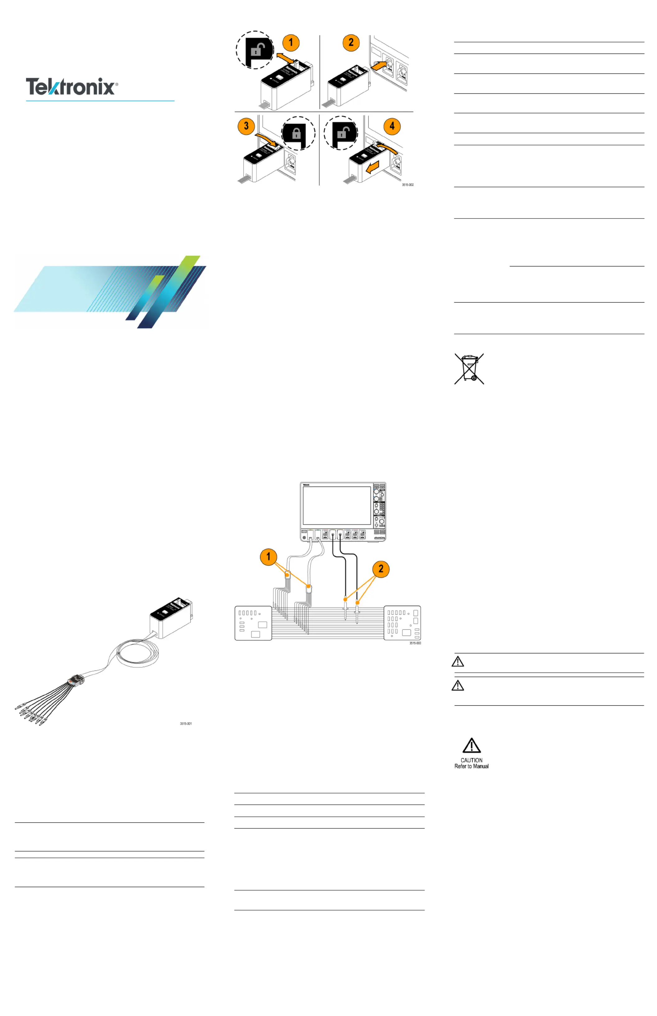
Connecting the probe to the oscilloscope
1. Move the locking lever to the unlocked position then let
go to reset locking lever to the center position.
2. Insert the probe into a FlexChannel channel until fully
seated and the lock mechanism clicks.
3. Mov
e the locking lever to the locked position. The status
light should be a solid green.
NOT
E. It is normal for the logic probe Status light to flash
green when the oscilloscope is powering on, and will turn to a
ste
ady green once the oscilloscope is fully running.
NOTE. If the status LED continues flashing green, ashingfl
red
, or is a steady red, contact Tektronix Customer Support
for assistance.
4. To r
emove the probe, move and hold the locking lever at
the unlocked position and pull out the probe.
Connecting the probe to your circuit
Attach the probe to the circuit using the connectors and adapters
shown on the back of these instructions. Select the best method
for your needs, and then go to Setting up the Probe.
Setting up the probe
The oscilloscope automatically detects and configures channels
when you connect a logic probe.
To set and view the digital channel parameters, add the channel
with the connected logic probe to the display. Double-tap
the Waveform badge for the logic probe channel to open the
configuration menu. Digital channel settings include threshold
voltage (default is 1.4 V), signal height (for all channels), and
channel labels.
Using the probe
See the oscilloscope documentation and Help topics for how to
display and trigger on digital logic signals and buses.
Functional check
Follow th
e instructions for connecting the probe to the
oscilloscope and setting up the probe. Connect your probe
leads to a
ctive logic signals on your DUT. You should see logic
activity immediately on all connected, active channels. If you
do not see
an active signal, use an analog probe to verify signal
activity on the logic signal points.
Typical
application
1. Use the logic probe to view digital signals on a system bus.
2. Use an analog probe to view analog waveform information
of a digital signal.
Accessories
The probe comes standard with a Logic Probe Accessory Kit
(Tektronix part number 020-3170-XX). See the illustration on
the following page. See the label in the accessories box lid for
information on the individual accessories.
Specifications
Table 1: Electrical and mechanical specifications
Characteristic Description
Input channels 8 digital
Inpu
t resistance
100 kΩ±1.0%
Input capacitance 3.0 pF
Input signal swing
Minimum 400 mV p-p
Maximum
30 V p-p, ≤200 MHz (centered around
the
DC threshold voltage) at the probe tip
10 V p-p, ≥200 MHz (centered around
the DC threshold voltage) at the probe tip
Max
imum nondest–
ructive input signal
30 V
p-p, ±42 V peak, ±50 V
DC
Characteristic Description
Threshold voltage ± 40 V
Minimum detectable
pulse width
1 ns
Maximum input
toggle rate
500 MHz
Maximum sample
rate
6.25 GS/s
Digital to analog
trigger skew
5 ns
Probe length
1.0 m (3.28 ft)
Table 2: En
vironmental specifications
Characteristic Description
Temperature
Operating
Nonoperating
0 °C to +50 °C (+32 °F to +122 °F)
–40 °C to +71 °C (–40 °F to +160 °F)
Humidity Noncondensing, and as limited by a maximum
Wet-Bulb temperature of +39 °C (+102 °F)
Operating 5% to 90% relative humidity to +40 °C (104 °F)
5% to 55% relative humidity +40 °C to +50 °C
(+104 °F to 122 °F)
Nonoperating
5% to 90% relative humidity to +40 °C
(+104 °F)
5% to 39% relative humidity +40 °C to +60 °C
(+104 °F to 140 °F)
Altitude
Operating
Nonoperating
3,000 m (9,842 ft) maximum
12,000 m (39,370 ft) maximum
Equipment Recycling. This symbol indicates that
this product complies with the applicable European
Union requirements according to Directives
2012/19/EU and 2006/66/EC on waste electrical
and electronic equipment (WEEE) and batteries.
For information about recycling options, check the
Tektronix Web site (www.tek.com/productrecycling).
Safety summary
Connect and disconnect properly. Connect the probe output
to the measurement instrument before connecting the probe
to the circuit under test. Disconnect the probe input and the
probe ground from the circuit under test before disconnecting
the probe from the measurement instrument.
Observe all terminal ratings. To avoid fire or shock hazard,
observe all ratings and markings on the product. Consult the
product manual for further ratings information before making
connections to the product. Connect the probe reference lead to
earth ground only.
Do not operate without covers.
Avoid exposed circuitry. Do not touch exposed connections
and components when power is present.
Do not operate with suspected failures. If you suspect there is
damage to this product, have it inspected by qualified service
personnel.
Do not operate in wet/damp conditions.
Do not operate in an explosive atmosphere.
Keep product surfaces clean and dry.
Safety terms and symbols in this manual.
These terms may appear in this manual:
WARNING. Warning statements identify conditions or
practices that could result in injury or loss of life.
CAUTION. Caution statements identify conditions or
practices that could result in damage to this product or
other property.
Symbols on the product. This symbol may appear on the
product:
Contacting Tektronix
Web site: www.tektronix.com
Phone: 1-800-833-9200
Address: Tektronix, Inc.
Department or name (if known)
14200 SW Karl Braun
Drive P.O. Box 500
Beaverton, OR 97077
USA
Email:
techsuppor[email protected]
War
ranty information
For warranty information, go to www.tektronix.com/warranty.
TLP058
FlexChannel
®
Logic Probe
Instruct
ions
x
1
*P0713
51503*
071-3515-03
Produktspezifikationen
| Marke: | Tektronix |
| Kategorie: | Nicht kategorisiert |
| Modell: | TLP058 |
Brauchst du Hilfe?
Wenn Sie Hilfe mit Tektronix TLP058 benötigen, stellen Sie unten eine Frage und andere Benutzer werden Ihnen antworten
Bedienungsanleitung Nicht kategorisiert Tektronix

1 August 2025
29 Juli 2025
17 Juli 2025
16 Juli 2025
9 Juli 2025
5 September 2024
5 September 2024
Bedienungsanleitung Nicht kategorisiert
- Elite Force
- Nethix
- Hazet
- Peerless
- Cadac
- ADATA
- Giordani
- Da-Lite
- Gra-Vue
- Radial Engineering
- Great Northern Popcorn
- Sinus Live
- Earthwise
- Eligent
- LOKUKA
Neueste Bedienungsanleitung für -Kategorien-
21 Januar 2026
21 Januar 2026
21 Januar 2026
21 Januar 2026
21 Januar 2026
21 Januar 2026
21 Januar 2026
21 Januar 2026
21 Januar 2026
21 Januar 2026