Valcom VIP-148AL Bedienungsanleitung
Valcom Lautsprecher VIP-148AL
Lies die bedienungsanleitung für Valcom VIP-148AL (5 Seiten) kostenlos online; sie gehört zur Kategorie Lautsprecher. Dieses Handbuch wurde von 13 Personen als hilfreich bewertet und erhielt im Schnitt 4.7 Sterne aus 9 Bewertungen. Hast du eine Frage zu Valcom VIP-148AL oder möchtest du andere Nutzer dieses Produkts befragen? Stelle eine Frage
Seite 1/5
1 947810
CAUTION: To reduce the risk of electric shock,
Do not remove cover.
No user serviceable parts inside.
Refer servicing to qualified service personnel.
CAUTION
RISK OF ELECTRIC SHOCK
DO NOT OPEN
This symbol indicates that dangerous
voltage constituting a risk of electric
shock is present within this unit.
This symbol indicates that there are
important operating and maintenance
instructions in the literature accompanying
this unit.
Issue 1
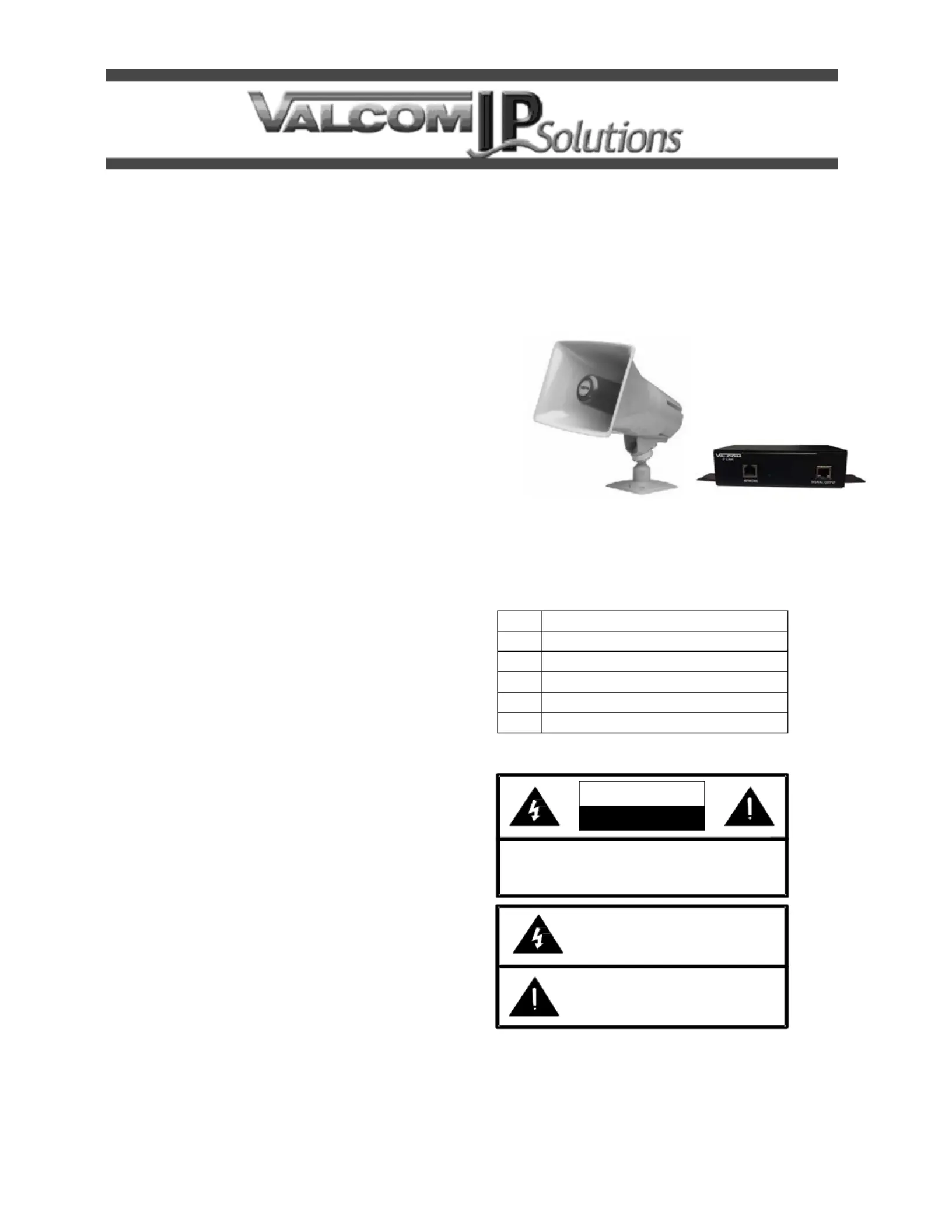
VIP-148AL IP Talkback Horn
INTRODUCTION
The VIP-148AL IP Talkback Horn enables
two-way handsfree voice access to a single
location over an IP-based network. This allows a
page zone extension anywhere on the network.
The horn audio level is electronically adjusted via
software. A call switch input connection is
provided for call initiation. Power is provided to
the VIP-148AL via a Power over Ethernet (PoE)
switch meeting the 802.3af specication.
SPECIFICATIONS
Access Methods
PBX, FXO Port w/VIP-811
POTS telephone set w/VIP-811
FXS Port w/VIP-821
SIP telephone system
Features
RJ-45 for network connection
Network activity LEDs
Power over Ethernet (PoE) 802.3af
compatible
Dimensions/Weight VIP-148AL
Horn
7.38” H x 10.0” W x 10.4” D
(18.75cm x 25.4cm x 26.42cm)
Weight: 3.70 lbs. (1.68 kg)
Network Interface
1.62” H x 5.63” W x 3.45” D
(4.11 cm) x (14.30 cm) x (8.73 cm)
with brackets– 8.22” W (20.87 cm)
Weight: 2.10 lbs. (0.95 kg)
Environment
Network Interface:
Temperature: 0 to +40° C
Humidity: 0 to 85% non-precipitating
Horn:
Suitable for indoor or outdoor installation
Nominal Power Requirements
Via 802.3af (PoE) Ethernet Switch: Class 3
Packing List
Qty Item
1 Network Interface
1 VIP-148AL Horn
1 VSP Document
1 “C” Clamp
1 VM-186 RJ-45 Connector
Precautionary Designations
Produktspezifikationen
| Marke: | Valcom |
| Kategorie: | Lautsprecher |
| Modell: | VIP-148AL |
Brauchst du Hilfe?
Wenn Sie Hilfe mit Valcom VIP-148AL benötigen, stellen Sie unten eine Frage und andere Benutzer werden Ihnen antworten
Bedienungsanleitung Lautsprecher Valcom

31 März 2026
27 März 2026
22 März 2026
19 März 2026
4 März 2026
29 November 2025
25 November 2025
8 Oktober 2025
25 September 2025
1 August 2025
Bedienungsanleitung Lautsprecher
Neueste Bedienungsanleitung für -Kategorien-
3 April 2026
3 April 2026
3 April 2026
3 April 2026
2 April 2026
2 April 2026
2 April 2026
2 April 2026
2 April 2026
2 April 2026