Yato YT-06175 Bedienungsanleitung
Yato Nicht kategorisiert YT-06175
Lies die bedienungsanleitung für Yato YT-06175 (2 Seiten) kostenlos online; sie gehört zur Kategorie Nicht kategorisiert. Dieses Handbuch wurde von 8 Personen als hilfreich bewertet und erhielt im Schnitt 4.4 Sterne aus 3 Bewertungen. Hast du eine Frage zu Yato YT-06175 oder möchtest du andere Nutzer dieses Produkts befragen? Stelle eine Frage
Seite 1/2
ZESTAW ŚCIĄGACZY BEZWŁADNOŚCIOWYCH DO WTRYSKIWACZY
DIESEL INJECTOR MASTER REMOVAL KIT
INJEKTOR AUSZIEHER ABZIEHER WERKZEUG EINSPRITZDÜSEN
СЪЕМНИКФОРСУНОКСУДАРНЫММОЛОТКОМДЛЯДИЗЕЛЬНЫХДВИГАТЕЛЕЙ
SOUPRAVA NA DEMONTÁŽ VSTŘIKOVAČŮ S REVERZNÍM KLADIVEM
SET DE EXTRACTOARE INERȚIALE PENTRU INJECTOARE
YT-06175
PL
EN
DE
RU
CZ
RO
CHARAKTERYSTYKA PRODUKTU
Zestaw ściągaczy bezwładnościowych do wtryskiwaczy służy do udarowego demontażu wtryskiwa-
czy paliwa z silników spalinowych. Dzięki załączonym do zestawu adapterom możliwy jest demontaż
wtryskiwaczy paliwa takich producentów, jak: Bosch, Delphi, Denso, Siemens. Możliwy jest także
demontaż pompowtryskiwaczy silników wysokoprężnych. Zestaw zawiera także dwa różne młotki
ślizgowe, co pozwala na łatwy demontaż nawet w ograniczonej przestrzeni.
Prawidłowa, niezawodna i bezpieczna praca jest zależna od właściwej eksploatacji produktu, dla-
tego:
Przed rozpoczęciem pracy należy przeczytać instrukcję i zachować ją.
Za szkody powstałe w wyniku nie przestrzegania przepisów bezpieczeństwa i zaleceń niniejszej
instrukcji, dostawca nie ponosi odpowiedzialności.
ZAWARTOŚĆ ZESTAWU
1. młotek ślizgowy 3,5 kg z trzpieniem dł. 400 mm
2. młotek ślizgowy 1,3 kg z trzpieniem dł. 150 mm
3. rękojeść
trzpienia młotka 3,5 kg
4. złącze przegubowe
5. trzpieniowy klucz sześciokątny 10 mm
6. adaptery „męskie” M [mm]: 10 x 1,5; 16 x 1,5; 17x1; 20x1; 25x1; 27x1
7. adaptery „żeńskie” F [mm]: 14x1,5; 27x1 (3 elementy)
8. adaptery sześciokątne [mm]: 17 (10x1,5 F); 21 (14x1,5 F)
9. adaptery typu „C” i typu „J” – do pompowtryskiwaczy
10. adapter kłowy
11. klucze nasadowe do pokryw wtryskiwaczy, rozmiar zabieraka 1/2” (12,5 mm) [mm]: 25, 27; 29; 30
INSTRUKCJA BEZPIECZEŃSTWA
Ostrzeżenie! Zachować szczególną ostrożność przy wszelkich pracach związanych z ukła-
dem paliwowym. Opary paliwa sąłatwopalne i nieostrożność pracy może prowadzić do po-
żaru lub nawet wybuchu.
Uwaga! Niniejsza instrukcja pokazuje tylko przykładowy sposób demontażu wtryskiwaczy paliwa.
Zawsze należy kierować się wskazówkami zawartymi w dokumentacji dołączonej do wtryskiwaczy
paliwa i/ lub silnika.
Przed rozpoczęciem pracy sprawdzić zawartość zestawu pod katem uszkodzonych i zagubionych
części. Zabroniona jest praca uszkodzonym lub zdekompletowanym zestawem.
Przed rozpoczęciem pracy należy odłączyć układ zapłonowy silnika oraz akumulator.
Przed rozpoczęciem pracy należy się upewnić, że układ paliwowy nie znajduje się pod ciśnieniem.
Podczas sprawdzania i ewentualnego rozładowania ciśnienia należy postępować zgodnie z doku-
mentacją dołączoną do silnika.
Pracować tylko w dobrze wentylowanych pomieszczeniach. Unikać gromadzenia oparów paliwa.
W trakcie pracy stosowaćśrodki ochrony osobistej takie, jak: okulary, rękawice, obuwie ochronne
oraz strój z długimi rękawami i nogawkami.
Produkt utrzymywać w czystości, w miejscu niedostępnym dla osób postronnych, a zwłaszcza dzieci.
OBSŁUGA PRODUKTU
Przed rozpoczęciem pracy należy wybrać jeden z dwóch młotków ślizgowych. Wybór młotka zależy
od dostępności miejsca. Tam gdzie nie jest możliwe użycie większego młotka, należy użyć mniej-
szego.
W przypadku wyboru większego młotka na gwintowany koniec trzpienia należy nakręcić rękojeść
(I).
Niezależnie od wybranego młotka ślizgowego jeden z końców trzpienia posiada gwint wewnętrzny
do którego należy przykręcić złącze przegubowe (I). Młotek jest gotowy do pracy.
Demontaż wtryskiwaczy paliwa
Uwaga! Nie stosować kluczy udarowych do przykręcania lub odkręcania elementów opisanego w
dalszej części instrukcji. Wszystkie połączenia skręcać i rozkręcać za pomocą kluczy ręcznych lub
rąk.
Przed rozpoczęciem demontażu wtryskiwaczy, należy dokładnie oczyścić miejsce demontażu z za-
nieczyszczeń i nagaru.
Przed rozpoczęciem demontażu należy odkręcić pokrywę za pomocą jednego z kluczy nasadowych
dopasowanych do rozmiaru nakrętki pokrywy (II).
Jeżeli wewnątrz korpusu wtryskiwacza znajduje się tuleja, przed rozpoczęciem demontażu wtryski-
wacza, należy ją wykręcić za pomocą trzpieniowego klucza sześciokątnego.
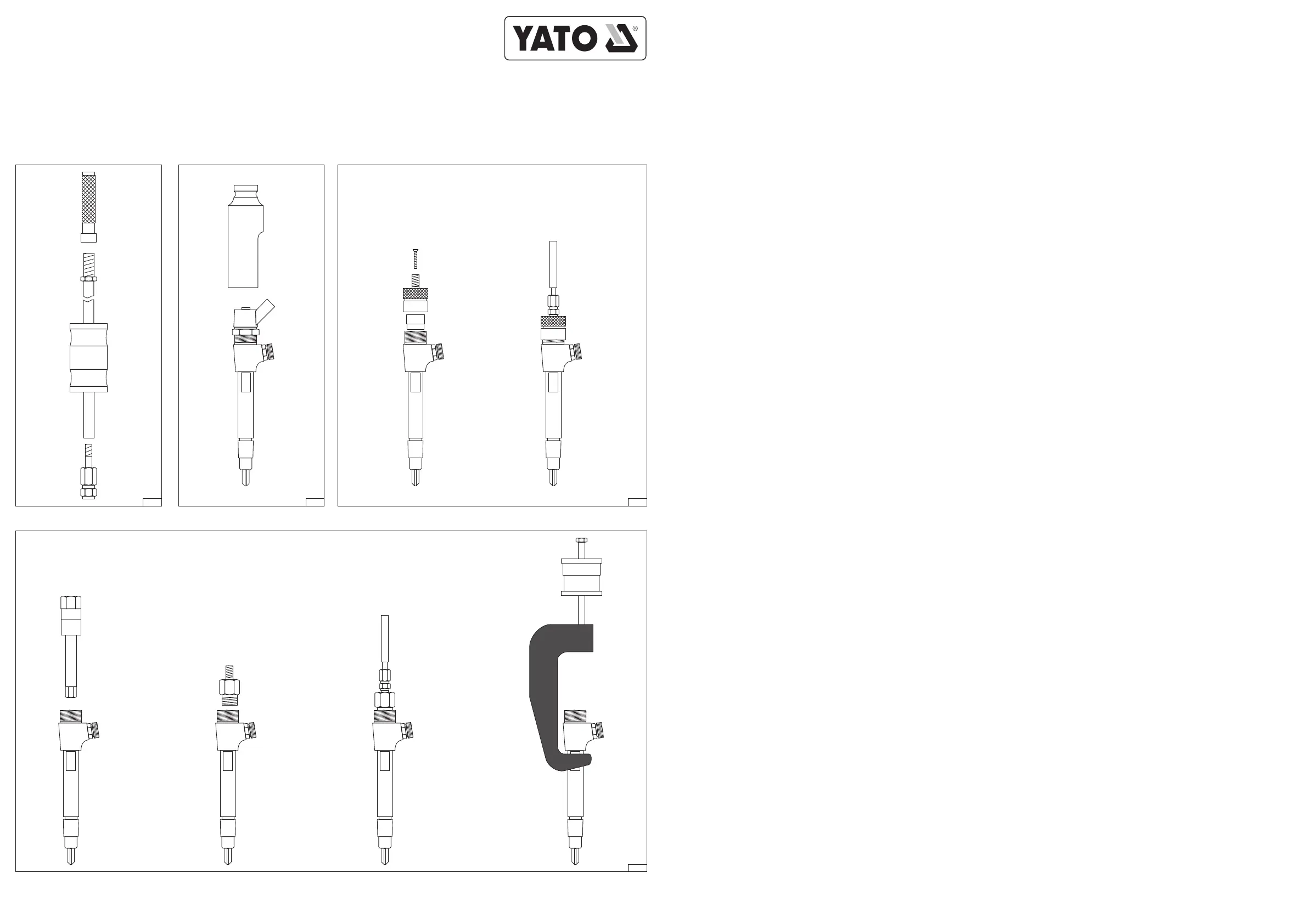
Następnie w zależności od typu wtryskiwacza należy wybrać odpowiedni adapter, który pozwoli na
przykręcenie złącza przegubowego zamontowanego na młotku ślizgowym do korpusu wtryskiwacza
Przykładowe sposoby połączenia pokazana na ilustracji (III).
Po połączeniu młotka i korpusu wtryskiwacza. Młotek obniżyć maksymalnie na trzpieniu, a następnie
gwałtownie przesunąć po trzpieniu, aż do uderzenia w element oporowy. Udar powstały podczas
uderzenia pozwoli zdemontować korpus wtryskiwacza. Jeżeli nie udało się zdemontować wtryskiwa-
cza przy pierwszym uderzeniu należy czynność powtórzyć.
Uwaga! Nie należy trzymać palców oraz innych części ciała na drodze ruchu młotka ślizgowego.
Uderzenie m
łotkiem ślizgowym może prowadzić do poważnych obrażeń.
Należy być gotowym na gwałtowną reakcję podczas „uwalniania” korpusu wtryskiwacza z gniazda.
Należy przyjąć postawę gwarantującą utrzymanie równowagi w takim przypadku.
KONSERWACJA I PRZECHOWYWANIE
Po każdym użyciu produkt dokładnie oczyścić, za pomocą miękkiej czystej tkaniny. Szczególną
uwagę należy zwrócić na oczyszczanie gwintów. Następnie nanieść na wszystkie elementy płyn
konserwujący lub lekki olej maszynowy, a jego nadmiar wytrzeć za pomocą miękkiej czystej tkaniny,
pozwoli to ograniczyć korozję produktu.
Produkt chronić przed wilgocią, przechowywać w oryginalnym opakowaniu w zacienionym miejscu z
dobrą wentylacją. Miejsce przechowywania powinno chronić przed dostępem osób niepowołanych,
a zwłaszcza dzieci.
PRODUCT CHARACTERISTICS
Set of the inertia pullers for injectors is used to the hammer disassembly of fuel injectors from internal
combustion engines. Due to the attached set of controllers, it is possible to dismantle fuel injectors
such producers, as: Bosch, Delphi, Denso, Siemens. It is also possible to disassembly the injector
units of diesel engines. The set includes two different slide hammers, which allows for an easy
removal even in a limited space.
Correct, reliable and safe operation of the device is dependent on its proper use, therefore:
Before beginning your work, you should read the manual and keep it around.
For any damage caused by failure to comply with safety regulations and instructions of this manual,
the supplier does not accept any liability.
CONTENTS OF THE SET
1. slide hammer 3.5 kg with the mandrel of length 400 mm
2. slide hammer 1.3 kg with the mandrel of length 150 mm
3. handle of the hammer mandrel 3.5 kg
4. articulated connector
5. socket screw key 10 mm
6. “male” adapters M [mm]: 10 x 1,5; 16 x 1,5; 17x1; 20x1; 25x1; 27x1
7. “female” adapters F [mm]: 14 x 1, 5; 27x1 (3 items)
8. hexagonal adapters M [mm]: 17 (10x1,5 F); 21 (14x1,5 F)
9. Adapters of the type “C” and type “J” - for the fuel injectors
10. laniary adapter
11. socket wrenches for the injectors lids, the size of the driver 1/2 “(12.5 mm) [mm]: 25, 27; 29; 30
SAFETY INSTRUCTION
Warning! Take special care when you perform any work related to the fuel system. Fuel va-
pours are fl ammable and carelessness can lead to fi re or even explosion.
Attention! This manual only shows an example of how to disassemble the fuel injectors. Always
follow the instructions included in the documentation that came with your fuel injectors and/or with
engine.
Before starting your work you should check the set contents for damaged and lost parts. It is prohib-
ited to operate a damaged or incomplete set.
Before starting work, you should disconnect the ignition the engine and battery.
Before every operation, you should ensure that the fuel system is not under pressure. When you
check and possible discharge pressure, you should follow the documentation that came with your
engine.
Work only in well ventilated rooms. Avoid accumulation of fuel vapor.
In the course of work you should use the personal protective equipment such glasses gloves, safety
shoes, and a dress with long sleeves and legs.
The product should be kept clean, in a place out of reach for bystanders, especially children.
PRODUCT SERVICE
Before starting work, you must choose one of the two slide hammers. Selection of hammer depends
on the availability of space. Where it is not possible to use a heavier hammer, you should use lighter
one.
If you choose a heavier hammer on the threaded end of mandrel you should screw the handle (I).
Regardless of the selected of slide hammer one end of the mandrel has an internal thread which
should be used to screw the articulated connection (I). The hammer is ready for use.
Disassembly of the fuel injectors
Attention! Do not use the impact wrenches to tighten or loosen the elements which are described
later in this manual. All connections should be screwed and unscrewed with manual wrenches or
by hand.
Before starting the disassembly of fuel injectors, you should thoroughly clean the dismantling place
of dirt and carbon deposits.
Before starting the disassembly, unscrew the cover with one of the socket wrenches which is se-
lected to fi t the size of the cover nuts (II).
If the inside of the injector body is a sleeve, before starting the disassembly of fuel injector, you
should remove it with the hexagonal socket screw key.
Then, depending on the type of injector, you should select the appropriate adapter, which will allow
you to screwing articulated connector mounted on the slide hammer to the injector. Sample methods
for connection are shown on the illustration (III).
After you connect the hammer and injector body. Lower the hammer to reduce on the mandrel as
much as possible, and then suddenly move it on the mandrel, until it hits a resistance element.
Stroke, which was created during the impact, will allow to remove the injector body. If you do not
manage to remove the injector at the fi rst stroke, yous should repeat it.
Attention! Do not hold your fi ngers and other parts of your body on the way of sliding hammer move-
ment. The stroke of slide hammer can lead to a serious injury.
You should be ready for a violent reaction during the “release” of injector body from its socket. You
should adopt the body position, that would ensure the maintenance of body balance in this situa-
tion.
MAINTENANCE AND STORAGE
After each use, you should clean the product thoroughly, using a soft clean cloth. Particular attention
should be paid to cleaning up the threads. Then apply to all the elements of a liquid preservative
or light machine oil, and its excess wipe out with a soft clean cloth. This will reduce the corrosion
product.
Protect the product against moisture, store it in its original packaging in a shaded place with good
ventilation. The storage should protect the product against access of unauthorized persons, espe-
cially children.
PLEN
TOYA S.A. ul. Sołtysowicka 13-15, 51-168 Wrocław, Polska
IIIIII
III
Produktspezifikationen
| Marke: | Yato |
| Kategorie: | Nicht kategorisiert |
| Modell: | YT-06175 |
Brauchst du Hilfe?
Wenn Sie Hilfe mit Yato YT-06175 benötigen, stellen Sie unten eine Frage und andere Benutzer werden Ihnen antworten
Bedienungsanleitung Nicht kategorisiert Yato

2 April 2026
1 April 2026
1 April 2026
1 April 2026
29 März 2026
28 März 2026
23 März 2026
22 März 2026
21 März 2026
21 März 2026
Bedienungsanleitung Nicht kategorisiert
Neueste Bedienungsanleitung für -Kategorien-
3 April 2026
3 April 2026
3 April 2026
3 April 2026
3 April 2026
3 April 2026
3 April 2026
3 April 2026
3 April 2026
3 April 2026