Emko EPR-3790-N Bedienungsanleitung
Emko Nicht kategorisiert EPR-3790-N
Lies die bedienungsanleitung für Emko EPR-3790-N (2 Seiten) kostenlos online; sie gehört zur Kategorie Nicht kategorisiert. Dieses Handbuch wurde von 20 Personen als hilfreich bewertet und erhielt im Schnitt 4.5 Sterne aus 2 Bewertungen. Hast du eine Frage zu Emko EPR-3790-N oder möchtest du andere Nutzer dieses Produkts befragen? Stelle eine Frage
Seite 1/2
YourTechnologyPartner
www.emkoelektronik.com.tr
Thankyouverymuchforyourpreferenceto
useEmkoElektron�kproducts,pleasev�s�tour
webpagetodownloaddeta�ledusermanual.
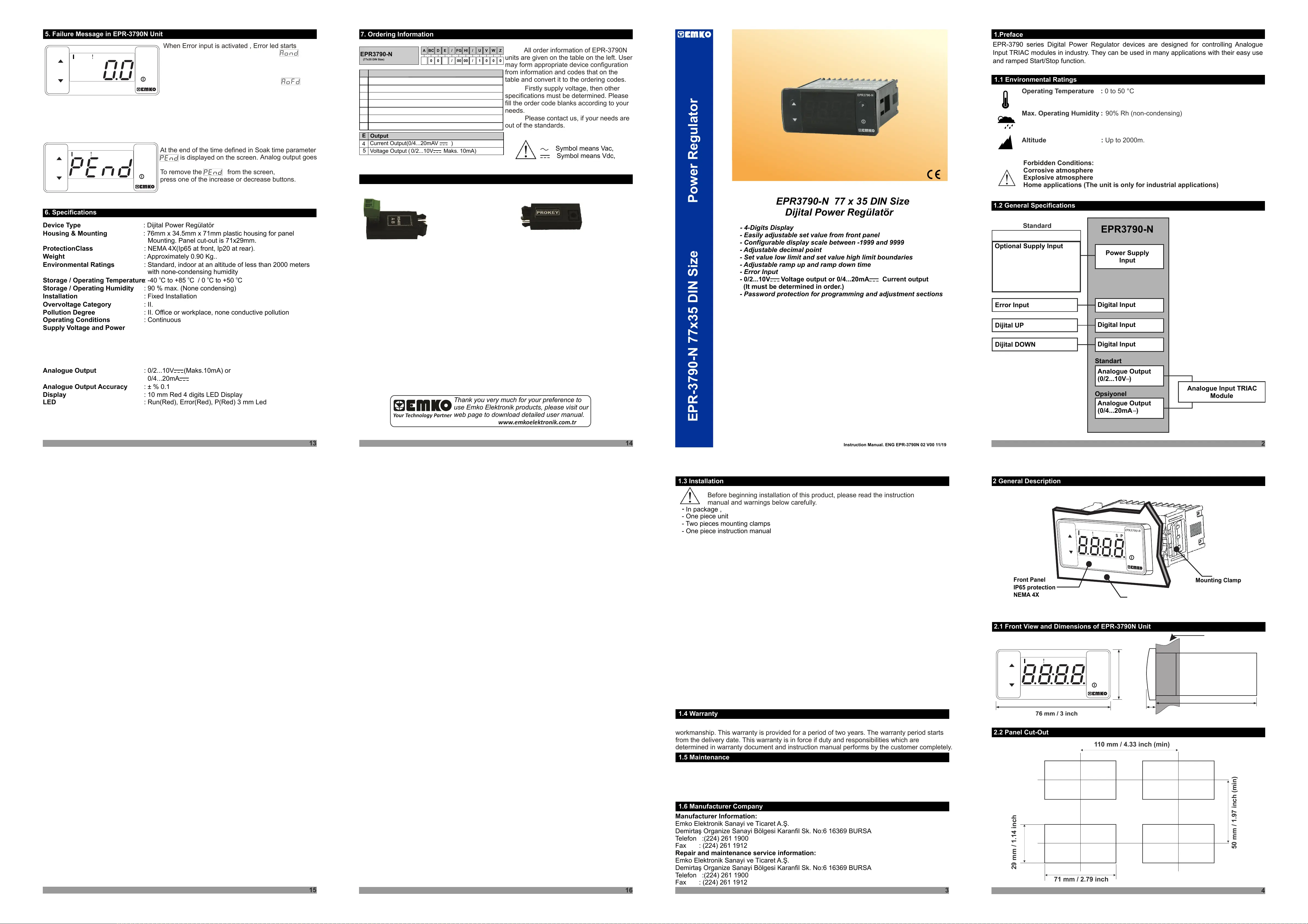
EPR-3790-N77x35DINS�zePowerRegulator
-4-D�g�tsD�splay
-Adjustabledec�malpo�nt
-Setvaluelowl�m�tandsetvalueh�ghl�m�tboundar�es
-Adjustablerampupandrampdownt�me
-Eas�lyadjustablesetvaluefromfrontpanel
-Conf�gurabled�splayscalebetween-1999and9999
-ErrorInput
-
-Passwordprotect�onforprogramm�ngandadjustmentsect�ons
0/2...10VZVoltageoutputor0/4...20mAZCurrentoutput
(Itmustbedeterm�ned�norder.)
EPR3790-N77x35DINS�ze
D�j�talPowerRegülatör
Instruct�onManual.ENGEPR-3790N02V0011/19
1.Preface
1.2GeneralSpec�f�cat�ons
2
EPR3790-N
Ops�yonel
Standart
AnalogueOutput
(0/2...10V)
AnalogueOutput
(0/4...20mA)
D�g�talInput
AnalogueInputTRIAC
Module
D�j�talDOWN
PowerSupply
Input
Standard
Opt�onalSupplyInput
Operat�ngTemperature:
Max.Operat�ngHum�d�ty:
Alt�tude:
0to50°C
90%Rh(non-condens�ng)
Upto2000m.
Forb�ddenCond�t�ons:
Corros�veatmosphere
Explos�veatmosphere
Homeappl�cat�ons(Theun�t�sonlyfor�ndustr�alappl�cat�ons)
1.1Env�ronmentalRat�ngs
3
-
Inpackage,
-Onep�eceun�t
-Twop�ecesmount�ngclamps
-Onep�ece�nstruct�onmanual
Beforebeg�nn�ng�nstallat�onofth�sproduct,pleasereadthe�nstruct�on
manualandwarn�ngsbelowcarefully.
1.3Installat�on
2.1FrontV�ewandD�mens�onsofEPR-3790NUn�t
2.2PanelCut-Out
110mm/4.33�nch(m�n)
50mm/1.97�nch(m�n)
29mm/1.14�nch
71mm/2.79�nch
2GeneralDescr�pt�on
4
13
14
16
6.Spec�f�cat�ons
Dev�ceType
Hous�ng&Mount�ng
Protect�onClass
We�ght
Env�ronmentalRat�ngs
Storage/Operat�ngTemperature
Storage/Operat�ngHum�d�ty
Installat�on
OvervoltageCategory
Pollut�onDegree
Operat�ngCond�t�ons
SupplyVoltageandPower
AnalogueOutput
AnalogueOutputAccuracy
D�splay
LED
:D�j�talPowerRegülatör
:76mmx34.5mmx71mmplast�chous�ngforpanel
Mount�ng.Panelcut-out�s71x29mm.
:NEMA4X(Ip65atfront,Ip20atrear).
:Approx�mately0.90Kg..
:Standard,�ndooratanalt�tudeoflessthan2000meters
w�thnone-condens�nghum�d�ty
:-40Cto+85C/0Cto+50C
:90%max.(Nonecondens�ng)
:F�xedInstallat�on
:II.
:II.Off�ceorworkplace,noneconduct�vepollut�on
:Cont�nuous
:0/2...10VZ(Maks.10mA)or
0/4...20mAZ
:±%0.1
:10mmRed4d�g�tsLEDD�splay
:Run(Red),Error(Red),P(Red)3mmLed
oooo
15
5.Fa�lureMessage�nEPR-3790NUn�t
WhenError�nput�sact�vated,Errorledstarts
7.Order�ngInformat�on
ABCDEFGHI/
/
U
VWZ/
/
000100
EPR3790-N
(77x35DINS�ze)
00
5
VoltageOutput(Maks.10mA)0/2...10VZ
Output
E
CurrentOutput(0/4...20mAVZ)
4
0
0
Allorder�nformat�onofEPR-3790N
un�tsareg�venonthetableontheleft.User
mayformappropr�atedev�ceconf�gurat�on
from�nformat�onandcodesthatonthe
tableandconvert�ttotheorder�ngcodes.
F�rstlysupplyvoltage,thenother
spec�f�cat�onsmustbedeterm�ned.Please
f�lltheordercodeblanksaccord�ngtoyour
needs.
Pleasecontactus,�fyourneedsare
outofthestandards.
VSymbolmeansVac,
ZSymbolmeansVdc,
workmansh�p.Th�swarranty�sprov�dedforaper�odoftwoyears.Thewarrantyper�odstarts
fromthedel�verydate.Th�swarranty�s�nforce�fdutyandrespons�b�l�t�eswh�chare
determ�ned�nwarrantydocumentand�nstruct�onmanualperformsbythecustomercompletely.
ManufacturerInformat�on:
Repa�randma�ntenanceserv�ce�nformat�on:
EmkoElektron�kSanay�veT�caretA.Ş.
Dem�rtaşOrgan�zeSanay�Bölges�Karanf�lSk.No:616369BURSA
Telefon:(224)2611900
Fax:(224)2611912
EmkoElektron�kSanay�veT�caretA.Ş.
Dem�rtaşOrgan�zeSanay�Bölges�Karanf�lSk.No:616369BURSA
Telefon:(224)2611900
Fax:(224)2611912
1.4Warranty
1.5Ma�ntenance
1.6ManufacturerCompany
Attheendofthet�medef�ned�nSoakt�meparameter
�sd�splayedonthescreen.
Analogoutputgoes
Toremovethefromthescreen,
pressoneofthe�ncreaseordecreasebuttons.
D�g�talInput
ErrorInput
D�g�talInput
D�j�talUP
EPR-3790ser�esD�g�talPowerRegulatordev�cesaredes�gnedforcontroll�ngAnalogue
InputTRIACmodules�n�ndustry.Theycanbeused�nmanyappl�cat�onsw�ththe�reasyuse
andrampedStart/Stopfunct�on.
Mount�ngClamp
FrontPanel
IP65protect�on
NEMA4X
EPR3790-N
76mm/3�nch
6mm/0.24�nch
34,5mm/1.36�nch
Max�mum15mm/0.59�nch
PS
EPR3790-N
65mm/2.56�nch
Panelsurface
(max�mumth�ckness15mm/0.59�nch)
PS
EPR3790-N
PS
EPR3790-N
8.Opt�onalAccessor�es
1-RS-485Module2.PROKEYProgrammingModule
RS-485Commun�cat�onInterface
Thedev�ce�sprogrammed(Uploador
Download)byus�ngtheparameters.
P
P
P
P
Av�sual�nspect�onofth�sproductforposs�bledamageoccureddur�ngsh�pment�s
recommendedbefore�nstallat�on.It�syourrespons�b�l�tytoensurethatqual�f�ed
mechan�calandelectr�caltechn�c�ans�nstallth�sproduct.
Ifthere�sdangerofser�ousacc�dentresult�ngfromafa�lureordefect�nth�sun�t,power
offthesystemandseparatetheelectr�calconnect�onofthedev�cefromthesystem.
Theun�t�snormallysuppl�edw�thoutapowersupplysw�tchorafuse.Usepowersw�tch
andfuseasrequ�red.
Besuretousetheratedpowersupplyvoltagetoprotecttheun�taga�nstdamageandto
preventfa�lure.
Keepthepoweroffunt�lallofthew�r�ng�scompletedsothatelectr�cshockandtrouble
w�ththeun�tcanbeprevented.
Neverattempttod�sassemble,mod�fyorrepa�rth�sun�t.Tamper�ngw�ththeun�tmay
results�nmalfunct�on,electr�cshockorf�re.
Donotusetheun�t�ncombust�bleorexplos�vegaseousatmospheres.
Dur�ngtheequ�pment�sputted�nholeonthemetalpanelwh�lemechan�cal�nstallat�on
somemetalburrscancause�njuryonhands,youmustbecareful.
Montageoftheproductonasystemmustbedonew�th�t’sf�x�ngclamps.Donotdothe
montageofthedev�cew�th�nappropr�atef�x�ngclamp.Besurethatdev�cew�llnotfall
wh�ledo�ngthemontage.
It�syourrespons�b�l�ty�fth�sequ�pment�sused�namannernotspec�f�ed�nth�s
�nstruct�onmanual.
A
PowerSupply
2
3
5
8
4
24VW(±%15)50/60Hz
24VV(±%15)50/60Hz
115VV(±%15)50/60Hz
230VV(±%15)50/60Hz
10-30VZ
:230VV(±%15)50/60Hz
:115VV(±%15)50/60Hz
:24VV(±%15)50/60Hz
:24VW(±%15)50/60Hz
:10-30VZ
230VV(±%15)50/60Hz
115VV(±%15)50/60Hz
24VV(±%15)50/60Hz
24VW(±%15)50/60Hz
10-30VZ
EMKOElektron�kwarrantsthattheequ�pmentdel�vered�sfreefromdefects�nmater�aland
dev�cebeforeaccess�ng�nternalparts.Donotcleanthecasew�thhydrocarbon-basedsolvent
PetrolTr�chlorethyleneetc.)Useofthesesolventscanreducethemechan�calrel�ab�l�tyofthe
dev�ce.Useaclothdampened�nethylalcoholorwatertocleantheexternalplast�ccase.
Repa�rsshouldonlybeperformedbytra�nedandspec�al�zedpersonnel.Cutpowertothe
bl�nk�ngafteraper�odoft�medef�ned�n
parameter.Ifthedev�ce�sstarted,theAnalog
outputrampsdowntom�n�mumsetl�m�t.
Aftererror�nputbecomespass�veerrorLed
turnsoffafteraper�odoft�medef�ned�n
parameter.(IfErrorlatch�ng�sselected�tturns
offwhenthedecrementbutton�spressedon
theOperat�onScreen.)Ifthedev�ce�sstarted,
theAnalogoutputrampsuptomax�mumset
l�m�t.
downsetlowerl�m�tfromthesetpo�nt.
9
CustomerSpec�f�ed
1
100-240VV50/60Hz(-%15;+%10)-6VA
:100-240VV50/60Hz(-%15;+%10)-6VA
100-240VV50/60Hz-6VA
Produktspezifikationen
| Marke: | Emko |
| Kategorie: | Nicht kategorisiert |
| Modell: | EPR-3790-N |
Brauchst du Hilfe?
Wenn Sie Hilfe mit Emko EPR-3790-N benötigen, stellen Sie unten eine Frage und andere Benutzer werden Ihnen antworten
Bedienungsanleitung Nicht kategorisiert Emko

20 September 2025
8 September 2025
8 September 2025
8 September 2025
7 September 2025
7 September 2025
7 September 2025
7 September 2025
7 September 2025
7 September 2025
Bedienungsanleitung Nicht kategorisiert
Neueste Bedienungsanleitung für -Kategorien-
3 April 2026
3 April 2026
3 April 2026
3 April 2026
3 April 2026
3 April 2026
3 April 2026
3 April 2026
3 April 2026
3 April 2026