Velbus VMBSTART-B-10 Bedienungsanleitung
Velbus
Nicht kategorisiert
VMBSTART-B-10
Lies die bedienungsanleitung für Velbus VMBSTART-B-10 (5 Seiten) kostenlos online; sie gehört zur Kategorie Nicht kategorisiert. Dieses Handbuch wurde von 4 Personen als hilfreich bewertet und erhielt im Schnitt 4.5 Sterne aus 2.5 Bewertungen. Hast du eine Frage zu Velbus VMBSTART-B-10 oder möchtest du andere Nutzer dieses Produkts befragen? Stelle eine Frage
Seite 1/5

Quick start guide VMBSTART-x-10
Pagina van 1 5
Congratulations on your purchase of the Velbus Starter Kit!
This quick start guide will walk you through the installation step by step.
Need a more detailed manual? Scan the QR code to access the
product page and find additional support under the "Support" tab.
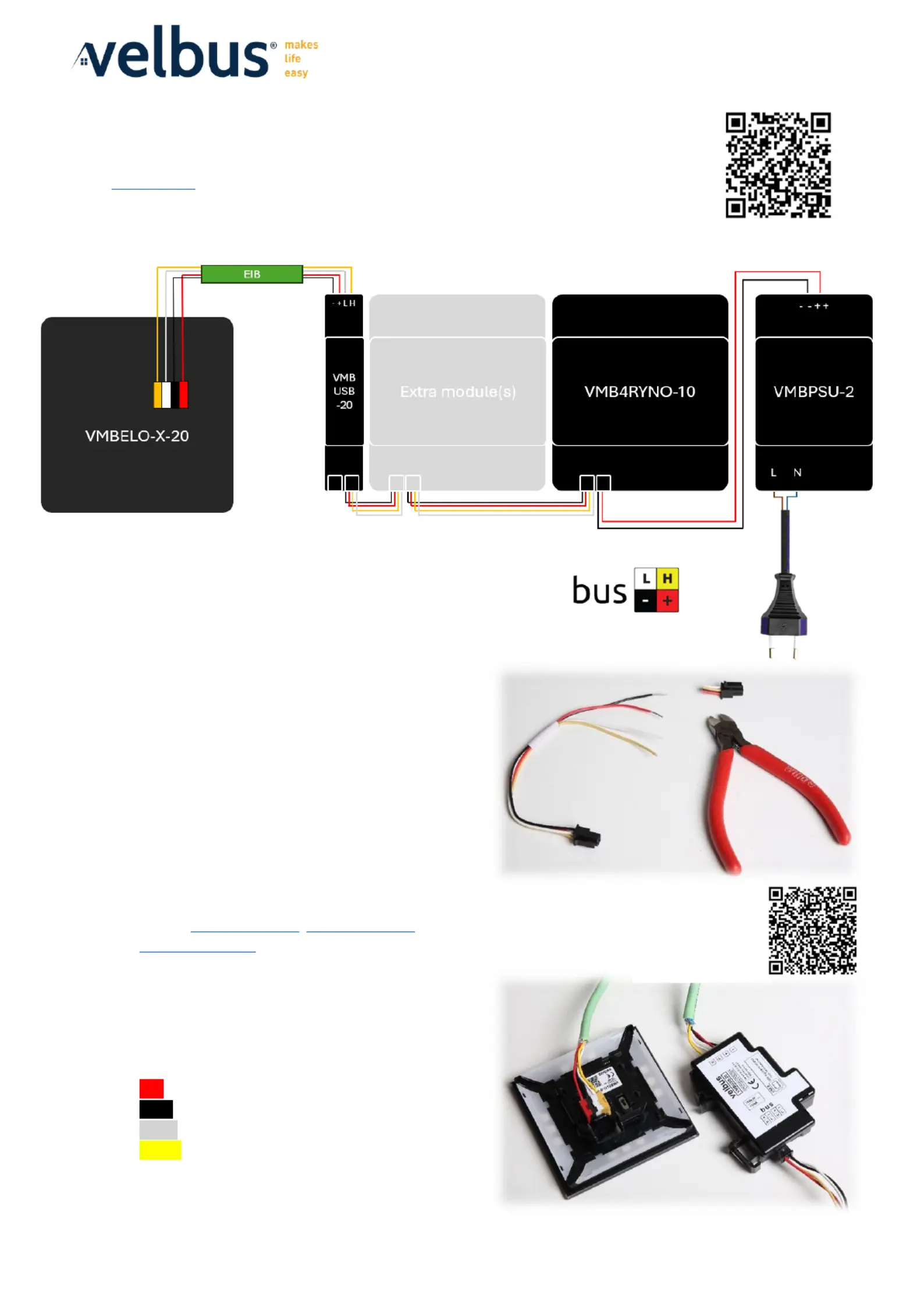
Step 1: Connecting the Components
Connect the components of the set as shown on the connection diagram:
Important notes:
• You can add multiple Velbus DIN rail modules between
the VMBUSB and VMB4RYNO modules.
• Use the included Molex cable to connect the
VMB4RYNO module to the VMBPSU module. Cut off
one side of the Molex connector, strip the black (-)
and red (+) wires, and connect them to the VMBPSU.
• The Molex connections on the VMB4RYNO and
VMBUSB modules are internally connected. It does
not matter which port you use.
• Each DIN rail module comes with a Molex cable for
daisy-chaining the bus. Need additional (longer) cables?
See our and VMBCABLE20SET, VMBCABLE40SET
VMBCABLE150SET.
• Strip both ends of the EIB cable and connect them to
the connectors on the VMBELO and VMBUSB
modules. Follow the color coding of the bus
connections:
Red Voltage 15V (± 3V) +
Black Voltage - 0V
White CANbus Low L
Yellow CANbus High H
Overview cable sets:

Quick start guide VMBSTART-x-10
Pagina van 2 5
Step 2: Configuring the Terminators
All Velbus modules (except the VMBUSB-20) are equipped with a terminator (a switch marked "TERM") that is
open by default. In every Velbus installation, at least two terminators must be closed, with as much cable
distance as possible between them. These are usually the first and last (farthest) modules in the installation.
For DIN rail modules, open the front panel to access the terminator. For other modules, the terminator is
located on the back. The terminator is enabled when the corresponding LED is lit.
In this basic setup, close the terminator on both the VMBELO panel and the VMB4RYNO module.
Step 3: Checking the BUS Connection
Velbus is a highly stable system, but any issues are usually caused by poor BUS connections.
Always perform the following check during the initial installation and after any cabling changes:
Press any button on a module (except the RESET button). You will see the LED next to the TX (transmit)
marking light up briefly. At the same time, the RX (receive) LEDs on all other modules in your installation will
also briefly light up. This indicates that a signal from the module is correctly placed on the bus and received by
the other modules.
Repeat this test for all other modules in your installation (except for the VMBUSB module, as it has no
buttons). If the other modules do not respond to the signal, double-check the cabling and follow our
troubleshooting guide.
Step 4: Programming via PC
• Download the latest Velbuslink software from . www.velbus.eu/downloads
The installation does not require admin rights unless you want to install the optional USB drivers.
• Connect the VMBUSB module to your computer using the included USB
cable after installing Velbuslink, and start the program.
• Click on "New" (top left) to start the "Create a new project" wizard.
Select for the following options: "Connect to an existing installation" Next
a "Direct connection via cable". nd

Quick start guide VMBSTART-x-10
Pagina van 3 5
During the scanning of the installation, you may allow automatic address assignment.
Do not do this if you are reading an existing (functioning) installation.
For a new project (as with this starter kit), you can choose to start with empty modules in this screen. For
an existing (functioning) installation, first read all the settings. Depending on the size of the installation,
this may take some time.
Once the reading process is complete, a confirmation message will appear, and you can start configuring.
• In the navigation panel, you will now see both the VMBELO and VMB4RYNO modules. You can expand the
channels of a module by clicking on the "+" symbol next to their names.
• Left- on the name of the selected module or channel to rename it. For example, change "Relay 1" to click
"Kitchen Light".
Produktspezifikationen
Marke: | Velbus |
Kategorie: | Nicht kategorisiert |
Modell: | VMBSTART-B-10 |
Brauchst du Hilfe?
Wenn Sie Hilfe mit Velbus VMBSTART-B-10 benötigen, stellen Sie unten eine Frage und andere Benutzer werden Ihnen antworten
Bedienungsanleitung Nicht kategorisiert Velbus
11 Juli 2025
10 Juli 2025
3 September 2024
3 September 2024
28 August 2024
21 August 2024
20 August 2024
20 August 2024
20 August 2024
20 August 2024
Bedienungsanleitung Nicht kategorisiert
- Dobot
- Monoprice
- Davey
- Adapt
- Reflexion
- EVOline
- Coxreels
- Primacoustic
- HABAU
- Ave Six
- V7
- Voltcraft
- Ixxat
- ProLights
- Tilta
Neueste Bedienungsanleitung für -Kategorien-
1 August 2025
1 August 2025
1 August 2025
1 August 2025
1 August 2025
1 August 2025
1 August 2025
1 August 2025