Canarm IFM318A13BK Bedienungsanleitung
Canarm Beleuchtung IFM318A13BK
Lies die bedienungsanleitung für Canarm IFM318A13BK (2 Seiten) kostenlos online; sie gehört zur Kategorie Beleuchtung. Dieses Handbuch wurde von 24 Personen als hilfreich bewertet und erhielt im Schnitt 4.8 Sterne aus 12.5 Bewertungen. Hast du eine Frage zu Canarm IFM318A13BK oder möchtest du andere Nutzer dieses Produkts befragen? Stelle eine Frage
Seite 1/2
INSTALLATION:
SAFETY PRECAUTIONS:
NOTE: Product may not look exactly as shown in figures.
Tel: (613) 342-5424, Fax: (800) 263-4598
IFM742B13
IFM318A13-EC
10/21
EASY CONNECT
INSTALLATION INSTRUCTIONS
TM
!
INSTRUCTIONS PERTAINING TO RISK OF FIRE OR INJURY TO PERSONS
READ ALL INSTRUCTIONS
IMPORTANT SAFETY
INSTRUCTIONS
SAVE THESE INSTRUCTIONS
TOOLS AND MATERIALS REQUIRED:
Phillips
Screwdriver
Wire Cutters
1. TURN OFF ELECTRICAL POWER BEFORE STARTING INSTALLATION OF LIGHT FIXTURE.
DO NOT REMOVE INSULATION FROM FIXTURE.
2. WIRING SUPPLIES AS REQUIRED BY LOCAL ELECTRICAL CODE.
3. THIS PRODUCT MUST BE INSTALLED IN ACCORDANCE WITH THE APPLICABLE INSTALLATION CODE BY
A PERSON FAMILIAR WITH THE CONSTRUCTION AND OPERATION OF THE PRODUCT AND THE
HAZARDS INVOLVED.
4. CAUTION – RISK OF FIRE. CONSULT A QUALIFIED ELECTRICIAN TO ENSURE CORRECT BRANCH
CIRCUIT CONDUCTOR.
5. TO CLEAN THE FIXTURE, TURN OFF THE POWER, WAIT FOR IT TO COOL, AND WIPE THE FIXTURE WITH
A CLEAN, SOFT CLOTH.
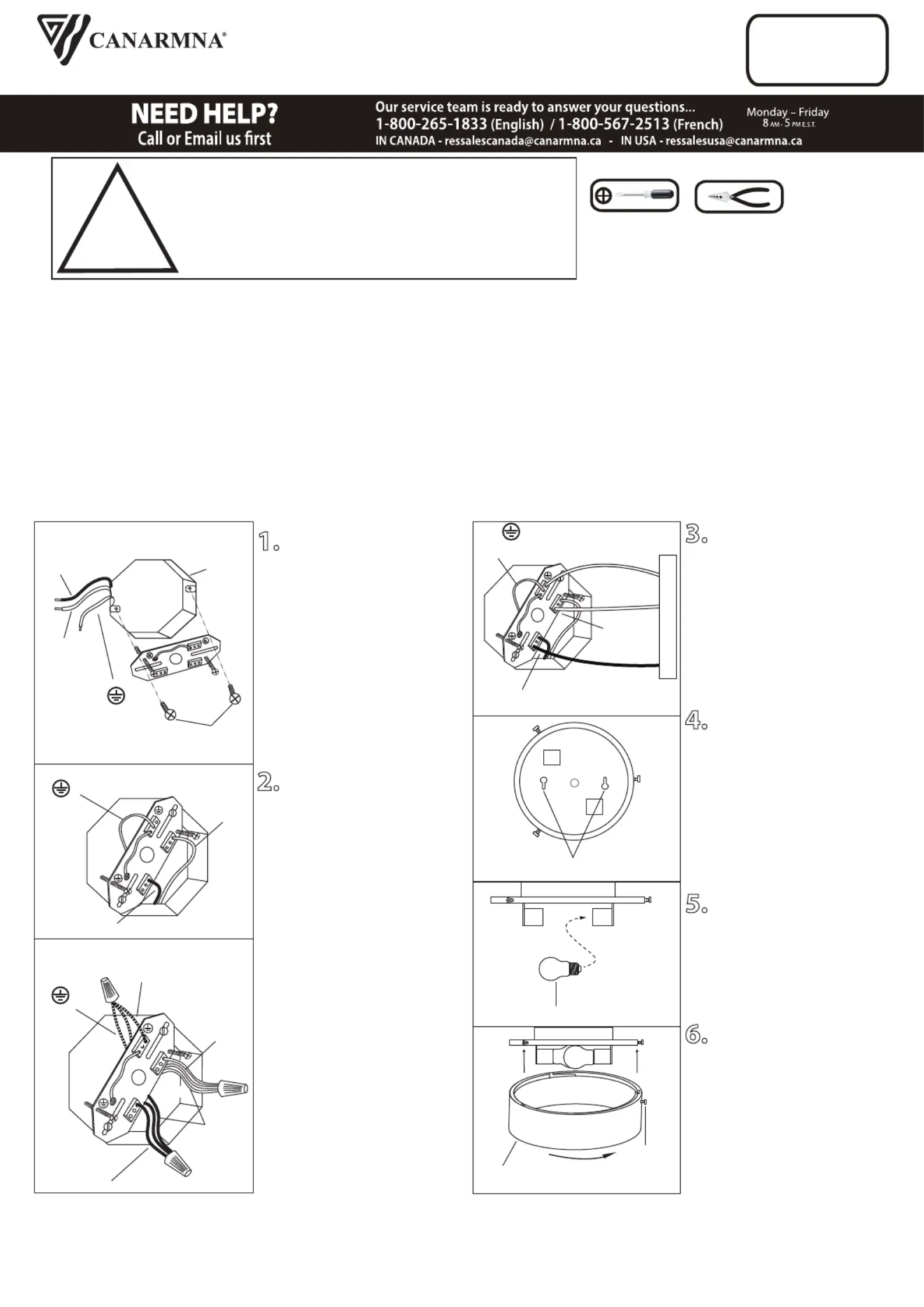
1. Install the mounting
bracket to the electrical box
using two electrical box
screws (not included). (Note:
Do not adjust the two
support screws at this time.)
2
. Option 1: Connect
(push) electrical wires from
electric box (house wiring)
into correct inserts.
Option 2: For multiple black
(live) & white (neutral) wires
joined in the electrical box
(house wiring), attach a single
“black” and “white” Jumper
Wire before connecting. Strip
7mm from a 6” Jumper Wires
supplied. Then connect
(push) wires into correct
inserts.
Electrical
Box
Electrical box
screws
(L)
Black (Live)
(N)
White
(Neutral)
Green
(Ground)
L
(L)
Black (Live)
(L)
Black (Live)
(N)
White
(Neutral)
(N)
White
(Neutral)
Green
(Ground)
Green
(Ground)
Jumper
Wire
Jumper
Wire
L
N
L
N
Option 1
Option 2
3. Connect (push) electrical
wires from fixture into correct
inserts.
4.Tuck the electrical wires
into the electrical box and
position the “key slots” over
the support screws. Turn and
lock the support screws into
the “key slots”. Tighten the
support screws into place.
5. Install the proper bulb
type and wattage (not
included).
6. Push the shade upward
and turn as shown. Lock the
shade by tightening thumb
screw against the fixture on
the side.
L
N
(L)
Black (Live)
(N)
White
(Neutral)
Green (Ground)
Fixture
Key Slots
Bulb
Thumb
screw
Shade
Produktspezifikationen
| Marke: | Canarm |
| Kategorie: | Beleuchtung |
| Modell: | IFM318A13BK |
Brauchst du Hilfe?
Wenn Sie Hilfe mit Canarm IFM318A13BK benötigen, stellen Sie unten eine Frage und andere Benutzer werden Ihnen antworten
Bedienungsanleitung Beleuchtung Canarm

20 Januar 2026
19 Januar 2026
19 Januar 2026
19 Januar 2026
19 Januar 2026
18 Januar 2026
17 Dezember 2025
16 Dezember 2025
16 Dezember 2025
16 Dezember 2025
Bedienungsanleitung Beleuchtung
Neueste Bedienungsanleitung für -Kategorien-
21 Januar 2026
21 Januar 2026
21 Januar 2026
21 Januar 2026
21 Januar 2026
21 Januar 2026
Philips Ultinon Drive 2001L LUMUD2001LX2 Bedienungsanleitung
21 Januar 2026 21 Januar 2026
21 Januar 2026
21 Januar 2026