Silent Knight SD500-MIM Bedienungsanleitung
Silent Knight Detektor SD500-MIM
Lies die bedienungsanleitung für Silent Knight SD500-MIM (2 Seiten) kostenlos online; sie gehört zur Kategorie Detektor. Dieses Handbuch wurde von 39 Personen als hilfreich bewertet und erhielt im Schnitt 4.1 Sterne aus 4 Bewertungen. Hast du eine Frage zu Silent Knight SD500-MIM oder möchtest du andere Nutzer dieses Produkts befragen? Stelle eine Frage
Seite 1/2
P/N 151071
SD500-AIM Input Module and
SD500-MIM Mini Input Module
Installation Instructions
The following instructions are a quick reference
guide, refer to the control panel installation
manual P/N 151139, 151274, 151280, 151295,
151209, or 151302 for detailed system
information.
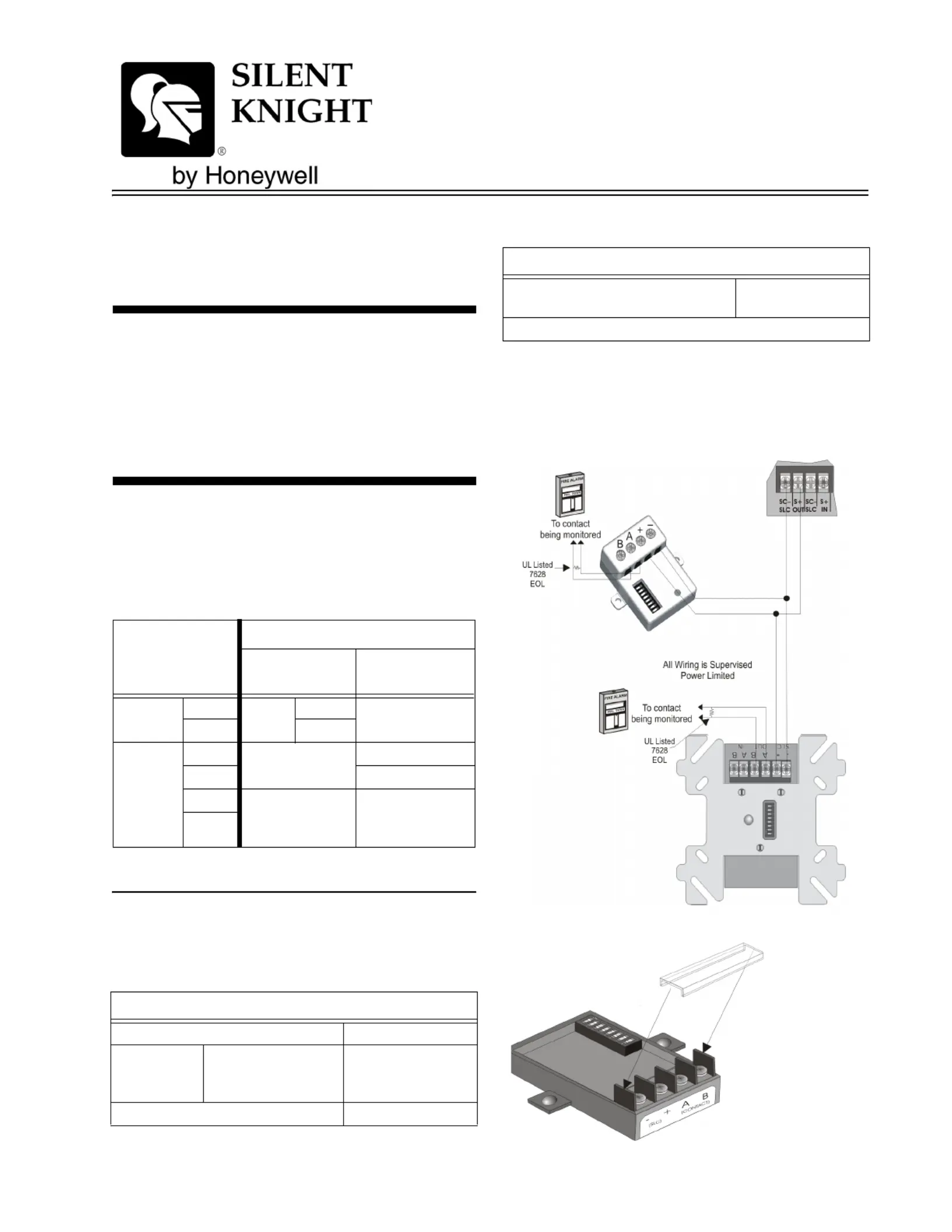
Wiring the SD500-AIM / MIM
Note:Installation and wiring of these devices must be done in
accordance with NFPA 72 and local ordinances.
Terminate the wiring as shown in Table 1. See
also Figure 1 or Figure 2
Specifications
Table 2 lists the operating specifications for the
SD500-AIM and the SD500-MIM.
Impedance for Earth Ground Fault is 0 Ω for all
terminals.
Figure 1: Class B Wiring the SD500-AIM & SD500-MIM
Table 1: Wire Connections
SD500-AIM
SD500-MIM
Terminals
To:
FACP or SLC
Loop Terminals
Contact
SLC
–
SLC
OUT
SC–
+S+
Contact
A out
CLASS A
OR B
To N.O. Contact
B outTo N.O. Contact
A IN
CLASS A ONLY
(SD500-AIM Only)
End of Loop A
End of Loop B
B IN
Table 2: SD500-AIM and SD500-MIM Specifications
Specifications
Max. Line resistance50Ω
Max. Alarm
Current
One device in alarm
23mA. 46 mA for two
devices in alarm.
.5 mA for each addi-
tional device in
alarm.
Max. Voltage33 V
Operating Temperature0° to 49° C
(32° to 120° F)
Indoor use only
Table 2: SD500-AIM and SD500-MIM Specifications
Specifications
Alternate
Construction
Produktspezifikationen
| Marke: | Silent Knight |
| Kategorie: | Detektor |
| Modell: | SD500-MIM |
| Breite: | 38 mm |
| Tiefe: | 18 mm |
| Gewicht: | 45.4 g |
| Höhe: | 64 mm |
| Menge pro Packung: | 1 Stück(e) |
Brauchst du Hilfe?
Wenn Sie Hilfe mit Silent Knight SD500-MIM benötigen, stellen Sie unten eine Frage und andere Benutzer werden Ihnen antworten
Bedienungsanleitung Detektor Silent Knight

30 August 2024
30 August 2024
30 August 2024
30 August 2024
30 August 2024
30 August 2024
Bedienungsanleitung Detektor
Neueste Bedienungsanleitung für -Kategorien-
30 März 2026
29 März 2026
23 März 2026
22 März 2026
21 März 2026
21 März 2026
20 März 2026
20 März 2026
20 März 2026
20 März 2026